
Instruction manual

Chapter 1 21
General Information
Required Equipment
1. General Information
Test Procedure
NOTE This procedure assumes the use of the recommended equipment model numbers. The
actual step required, therefore, may differ for other model numbers of equipment used.
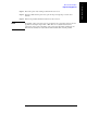
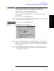
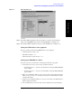
Step 1. Setup the equipment as shown in Figure 1-2.
a. Connect the DC REFERENCE OUTPUT connector on the rear panel of the range
calibrator to the DVM voltage input.
b. Connect the POWER METER output of the range calibrator to the input of the power
meter being tested.
c. Switch on the power to the power meter, the range calibrator, and the digital voltmeter.
Figure 1-2 Setup for the Power Meter Accuracy Test
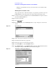
Step 2. Press the power meter: Press
[Preset/Local], then Confirm.
Step 3. Perform the following steps for each channel on the power meter:
a. Set to read in dBm: Press
[dBm/W], then dBm.
b. Set the ref cal factor to 100%: Press
[Zero/Cal], Cal, A/B Ref CF, then set to 100.0, if
necessary.
c. Set the cal factor to 100%: Press
[Frequency/Cal Fac], A/B Cal Fac, then set to 100.0,
if necessary.
d. Set readout to 0.001 dBm: Press
[Meas Setup], then Resolution 1234, to highlight 4.
e. Set filter step detect on and filter length to 512: Press
[System/Inputs], channel Aor B
Input Setting
, [More], Ch A/B Filter, Step Det On, Filter On, Mode MAN, Length,
then set the filter length to
512.
Step 4. Setup the digital voltmeter (DVM) as follows:
a. Reset the DVM: Press the
blue key followed by Reset.
b. Set the sample period to a value greater than one second: Press
NPLC, 5, 0, then Enter.
Step 5. Set the range calibrator controls as follows:
• POLARITY: NORMAL
• RANGE: 1 mW