
User`s guide


262 Chapter 10
GPS Modulation
GPS Operation
GPS Operation
This section guides you through the basic operation for using the real-time GPS option.
Setting Up the GPS Signal
If the signal generator is in the factory-defined preset mode, (Utility > Power On/Preset > Preset
Normal User
to Normal) a basic GPS signal will automatically be set up when the Preset key is
pressed, then performing step 2 and steps 6 through 8 will generate a signal at the RF
OUTPUT connector. To set up a signal using additional features of the GPS personality,
complete this procedure starting with step 1.
1. Press
Preset.
2. Press
Mode > More (1 of 2) > Real Time GPS.
3. Press
Satellite ID > 8 > Enter.
4. Press
Doppler Shift > 2.5 > kHz.
5. Press Data Mode Enc TLM to Enc.
6. Press
Data > PN Sequence > PN15.
To create a user file, refer to “Creating a User File” on page 143.
7. Press
Real-time GPS Off On to On.
8. Press the
Frequency hardkey. Using the numeric keypad, set the signal generator RF
output frequency to 1.57542 GHz (L1 carrier frequency).
9. Press the Amplitude hardkey. Using the numeric keypad, set the signal generator RF
output amplitude to
−120 dBm.
10.Turn the RF output on by pressing the
RF On/Off hardkey on the signal generator front
panel.
The real-time GPS signal is now available at the signal generator RF OUTPUT connector.
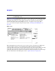
Figure 10-4 on page 263 shows what the signal generator display should like after all steps
have been completed. Notice the GPS, I/Q, and RF ON annunciators are on and the parameter
settings for the signal are displayed in the status area of the signal generator display.
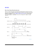
This task sets up a GPS signal that incorporates a subframe structure using 10 words, each
with 24 raw data bits and 6 parity bits computed from the data source. This subframe
structure was accomplished by selecting Enc as the data mode and using a PN15 sequence.
The PN15 sequence was encoded with the C/A code at 50 bps. Using factory preset settings,