
User`s guide


Chapter 15 355
W-CDMA Uplink Digital Modulation for Receiver Test
Understanding the PRACH
the additional power required when more UEs (user equipment/mobiles) are utilized (see
“Understanding the Power Offset Between the Carrier and the Multiple PRACH” on page 378
for more information).
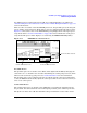
There are three areas that control the PRACH power level, the preamble power, the data part
power, and the control part power. Each of these areas are explained in the following sections.
Figure 15-7 shows these areas on the PRACH timing setup display while in the Pp-m power
setup mode. Refer to “Power Control Modes” on page 360 for more information on the power
setup modes. The power control display is accessed using the
PRACH Power Setup softkey.
Figure 15-7 PRACH Power Control Areas
Preamble Power
The preamble power is an absolute value (dBm) and is adjusted in the ESG by changing the
value in the Max Pwr field. Its value is used in determining the control part power level, which
influences the total message part power. See “Control Part Power” for more information.
The preamble power can be adjusted so that it exceeds the current carrier power. When this
occurs, the ESG will automatically adjust the carrier power. The reverse is also true when you
enter a new carrier power.
Control Part Power
The control part power is an absolute value (dBm) that is set indirectly and with respect to
the preamble. It is derived from the sum of the highest preamble power and the Pp-m value.
The Pp-m is an offset value (dB) that determines the power difference between the control
Controls the Data Part Power
Controls the Control Part Power
Controls the Preamble Power
Pp-m Power Mode Selected