
User`s guide


370 Chapter 15
W-CDMA Uplink Digital Modulation for Receiver Test
Generating a Single PRACH Signal
to perform a power search. Refer to “Special Power Control Considerations When Using
DPCCH/DPDCH in Compressed Mode or PRACH” on page 453 before completing this
procedure.
This procedure will teach you how to set up the AICH (acquisition indication channel) feature
so that it triggers the message part transmission. This procedure uses the ESG’s LF (low
frequency) output to simulate the AICH signal (TTL trigger), or if you prefer, an external
source can be used. Connecting the AICH trigger signal to the ESG requires the use of the
rear panel AUX I/O connector. (See “Rear Panel Overview” on page 18 for more information on
the AUX I/O connector.) An adapter will be needed to make the connection between the LF
OUTPUT and pin 17 on the AUX I/O connector.
Finding the Rear Panel Input for the AICH Signal
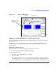
1. Press
Link Control > PRACH Rear Panel Setup > PRACH Input Signal Setup.
2. Find which rear panel connector accepts the AICH trigger.
The listed connector (Pattern trigger in 2 on AUX pin 17) is a pin on the AUX I/O
connector.
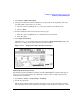
Changing the PRACH Output Trigger
Press
Return > PRACH Output Signal Setup > More (1 of 3) > More (2 of 3) > PRACH Pulse(RPS23).
This is being done so you can view the message part transmission on the PSA as the AICH is
received. The trigger output is on the EVENT 1 rear panel connector.
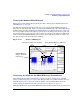
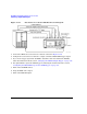
Connecting the ESG
Refer to Figure 15-17 and make the connections as shown.