
User`s guide


378 Chapter 15
W-CDMA Uplink Digital Modulation for Receiver Test
Multiple PRACH Overview
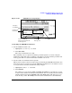
Preamble pulse This indicates the beginning of the access slot for each preamble
transmission.
Message pulse This signifies the start of an access slot where the message part is
being transmitted.
PRACH pulse This denotes the access slot boundaries between PRACH repetitions.
Refer to “PRACH Mode” on page 441 for more information on trigger signals.
Understanding the Power Offset Between the Carrier and the
Multiple PRACH
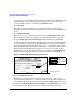
The ESG has an 18.06 dB offset between the ESG carrier power and the multiple PRACH
power level. This offset is shown by the PRACH power level in the PRACH Power Setup
display. This is demonstrated in Figure 15-22 where the carrier power is 0.0 dBm and the
PRACH power is
−18.06 dBm (0.0 dBm − (−18.06 dBm) = 18.06 dB offset). Since the data part
power has been turned off, the PRACH power is shown in both the Max Pwr field (preamble
power) and the Msg Pwr field (message part power) as indicated in the figure.
Figure 15-22 Offset Power
The offset is provided so the ESG can accommodate the additional power needed as more UEs
(user equipment/mobiles) are utilized. This offset remains constant on the ESG display
regardless of the number of UEs activated or parameter changes. However with the AWGN
feature on, the addition of noise to the PRACH signal will increase the offset. When this
condition occurs, the ESG carrier power will remain constant and the PRACH power level will
PRACH Power—18.06 dB Offset from Carrier Power
ESG Carrier Power