
Specifications


8
Parameter
Frequency
Amplitude
RF On/Off
Mode / (Real-time I/Q BaseBand)
CDMA
Phase Polarity
IQ Map Rotation
BBG Data Clock
BTS Setup
Filter
Even Second Delay
LC State
PN Offset
IQ Voltage Scale
Return
Link Control
Channel 1 (F-PICH) Setup:
Channel Number
Channel State
Channel Setup
Power
Return
Channel 2 (F-SYNCH) Setup:
Channel Number
Channel State
Channel Setup
Power
Walsh Code
Return
Channel 3 (F-FCH) Setup:
Channel Number
Channel State
Channel Setup
Power
Walsh Code
Radio Config
Return
Channel 4 (F-PCH) Setup:
Channel Number
Channel State
Channel Setup
Power
Walsh Code
Return
Channel Power Scaling:
Channel Setup
Adjust Code-Domain
Power
Return
Return
CDMA2000
I/Q
I/Q Source
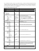
Table 2. ESG instrument configuration for one-box setup
Setting Notes
[900 MHz]
Set to the appropriate center frequency of the carrier
[-40 dBm]
Set to the appropriate amplitude desired
On
Normal
Std.
Int
Use the arrows to navigate to adjust the BTS (Basestation
Transceiver Station) Setup parameters.
IS95 w/ EQ
Set Filter to IS95 w/ EQ for either IS-95 or IS-2000
17.5
Set delay to 17.5 chips to align RF with the trigger.
[00000000000]
The LC (long code) State may be set to 00000000000 for no
[0]
long code or to 00000000001or another value to seed the long
0.00 dB
code.
IQ Voltage Scale is set to zero for the one-box setup.
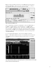
From the Link Control menu, setup the channels as follows.
Refer to Figure 4.
F-PICH (Forward Pilot Channel)
1
On
Use the arrows to navigate to adjust the Channel Setup
[-7.00 dB]
parameters. Walsh Code for Pilot Channel is fixed at 0.
F-SYNCH (Forward Sync Channel)
2
On
[-13.00 dB]
32
The Sync channel uses Walsh code 32.
F-FCH (Forward Fundamental Traffic Channel)
3
On
[-10.00 dB]
[8]
Walsh code range for RC1 Fundamental is 0 – 63.
[1]
F-PCH (Forward Paging Channel)
4
On
[-10.00 dB]
[1]
The initial paging channel is set to Walsh code 1.
This step scales the power levels of the active channel so
that they display the correct power levels being transmitted.
The ratios are kept the same. If your total power is equal to
Scale to 0 dB
0.00 dB, then this step may be skipped. This feature is only
used for the one-box solution.
On
For the one-box setup, the I/Q is set to internal.
On
Int I/Q
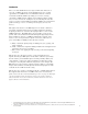
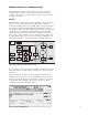
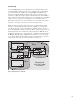
After configuring the hardware, follow the steps in Table 2 below to configure the instrument appropriately. In this
example, Pilot, Sync, Traffic, and Paging channels are defined. For IS-95, the traffic channel may be defined as RC1
or RC2. This example is intended to illustrate a basic set-up from which the user can customize the instrument to
meet his needs. Values in brackets [ ] are for example purposes only and the actual value should be determined by
the user. Hard key selections are indicated by bold text.