
User`s guide

Chapter 11 231
Peripheral Devices
N5102A Digital Signal Interface Module
Configuring the Clock Signal
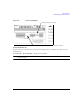
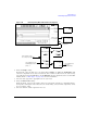
1. Press the
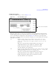
Clock Setup softkey, as shown in Figure 11- 17.
Figure 11-17 Clock Setup Menu Location
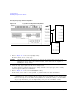
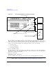
From this softkey menu, set all of the clock parameters that synchronize the data between the
N5102A module and the device. From this menu, the clock signal phase can be changed so the
clock occurs during the valid portion of the data. Figure 11- 18 shows the clock setup menu.
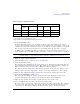
If the device or external clock does not match the frequency, one of the following error messages
will appear on the PSG:
803 Digital module input FIFO overflow error; There are more
samples being produced than can be consumed at the current
clock rate. Verify that the digital module clock is set up
properly.
This error is reported when the digital module clock setup is not
synchronized with the rate the samples are entering the digital
module. Verify that the input clock rate matches the specified
clock rate under the clock setup menu.
804 Digital module input FIFO underflow error; There are not enough
samples being produced for the current clock rate. Verify that
the digital module clock is set up properly.
This error is reported when the digital module clock setup is not
synchronized with the rate the samples are entering the digital
module. Verify that the input clock rate matches the specified
clock rate under the clock setup menu.
Accesses the Clock Setup Menu