
User`s guide

38 Chapter 2
Basic Operation
Configuring the RF Output
3. Change the amplitude to −20 dBm: Press Amplitude > −20 > dBm.
The new output power displays in the AMPLITUDE area of the display and in the active entry area.
Until you press a different front panel function key, amplitude remains the active function. You
can also change the amplitude using the up and down arrow keys or the knob.
Setting the Amplitude Reference and Amplitude Offset
The following procedure sets the RF output power as an amplitude reference to which all other
amplitude parameters are relative. The amplitude initially shown on the display is 0 dB (the power
output by the hardware minus the reference power). Although the display changes, the output power
does not change. Any subsequent power changes are shown as incremental or decremental to 0 dB.
1. Press
Preset.
2. Set the amplitude to −20 dBm: Press
Amplitude > -20 > dBm.
3. Activate the amplitude reference mode and set the current output power (−20 dBm) as the
reference value: Press
More (1 of 2) > Ampl Ref Set.
The AMPLITUDE area displays 0.00 dB, which is the power output by the hardware (−20 dBm)
minus the reference value (−20 dBm). The REF indicator activates and the
Ampl Ref Off On softkey
toggles On.
4. Turn the RF output on: Press
RF On/Off.
The display annunciator changes to RF ON. The power at the RF OUTPUT connector is −20 dBm.
5. Change the amplitude increment value to 10 dB: Press
Incr Set > 10 > dB.
6. Use the up arrow key to increase the output power by 10 dB.
The AMPLITUDE area displays 10.00 dB, which is the power output by the hardware
(- 20 dBm plus 10 dBm) minus the reference power (−20 dBm). The power at the RF OUTPUT
connector changes to −10 dBm.
7. Enter a 10 dB offset: Press
Ampl Offset > 10 > dB.
The AMPLITUDE area displays 20.00 dB, which is the power output by the hardware (−10 dBm)
minus the reference power (−20 dBm) plus the offset (10 dB). The OFFS indicator activates. The
power at the RF OUTPUT connector is still −10 dBm.
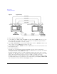
Configuring a Swept RF Output
A PSG signal generator has up to three sweep types: step sweep, list sweep, and ramp sweep
(Option 007).
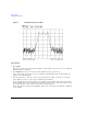
The signal generator indicates the sweep advance in a progress bar on the front- panel display. If the
sweep time is greater than one second, the progress bar sweep advances according to the frequency
span of each segment. For each segment in the span, the progress bar displays the full segment and
then the sweep is taken. With sweep times less than one second, the progress bar is drawn, the
sweep taken, and the progress bar is then blanked.