
User`s guide

Agilent X-Series Signal Generators User’s Guide 229
Basic Digital Operation (Option 653/655/656/657)
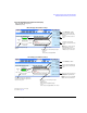
Multiple Baseband Generator Synchronization
generation, appropriately configure the trigger settings prior to selecting a signal generator as the
master or slave.
The system trigger propagates in the same manner as the synchronization pulse initiated by the
master (see System Synchronization). So if it is not turned off during changes to the synchronization
parameters, it can cause a false In Sync status.
The signal generator does not reset the trigger parameters when the multiple BBG synchronization
feature is turned off. To play waveforms after disabling the feature, you must either set the trigger
type to Free Run or provide a trigger to start the waveform play back.
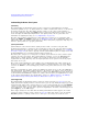
Equipment Setup
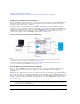
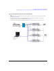
Figure 8-29 Multiple Baseband Synchronization Setup
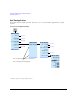
Configuring the Setup
Set the Common Parameters
Perform the following steps on all signal generators:
1. Set the frequency of the carrier signal.
2. Set the power level of the carrier signal.
3. Select the desired waveform (see page 148).
Do not turn the Dual ARB on.
There can be 1 to 15
slaves in a setup.
If not using the Trigger key, provide an external trigger
source. For information on the PAT TRIG connector,
see page 17.
PAT TRIG
PAT TRIG
PAT TRIG
10MHz Out
REF IN
10MHz Out
REF IN
REF IN
10MHz Out
EVENT 1
EVENT 1
EVENT 1
RF OUTPUT
RF OUTPUT
RF OUTPUT
RF OUTPUT
Note:
To minimize synchronization delay, the Agilent BNC cable 10502A is the recommended
cable for the rear panel daisy chain connections (see page 228).
PAT TRIG
or GPIB