
User`s guide


Agilent X-Series Signal Generators User’s Guide 255
Digital Signal Interface Module (Option 003/004)
Clock Timing
The levels will degrade above the warranted level clock rates, but they may still be usable.
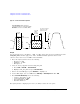
Serial Port Configuration Clock Rates
For a serial port configuration, the lower clock rate limit is determined by the word size (word size
and sample size are synonymous), while the maximum clock rate limit remains constant at 150 MHz
for LVTTL and CMOS logic types, and 400 MHz for an LVDS logic type.
The reverse is true for the sample rate. The lower sample (word) rate value of 1 kHz remains while
the upper limit of the sample rate varies with the word size. For example, a five- bit sample for an
LVTTL or CMOS logic type yields the following values in serial mode:
• Clock rate of 5 kHz through 150 MHz
• Sample rate of 1 kHz through 30 MHz
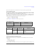
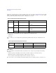
Refer to Table 10- 3 and Table 10- 4, for the serial clock rates.
Parallel and Parallel Interleaved Port Configuration Clock Rates
Parallel and parallel interleaved port configurations have other limiting factors for the clock and
sample rates:
•logic type
• Clocks per sample selection
• IQ or IF digital signal type
Clocks per sample (clocks/sample) is the ratio of the clock to sample rate. For an IQ signal type, the
Ta bl e 10-3 Output Serial Clock Rates
Logic Type Minimum Rate Maximum Rate
LVDS 1 x (word size) kHz 400 MHz
LVTTL and CMOS 1 x (word size) kHz 150 MHz
Tab le 10-4 Input Serial Clock Rates
Logic Type Data Type Minimum Rate Maximum Rate
LVDS Samples 1 x (word size) kHz 400
Pre- FIR
Samples
1 x (word size) kHz
the smaller of: 50
1
x (word size) MHz
or
400 MHz
1
The maximum sample rate depends on the selected filter when the data rate is Pre-FIR Samples. Refer to “Input Mode” on page 268 for more
information.
LVTTL and CMOS N/A 1 x (word size) kHz 150 MHz