
User`s guide

Agilent X-Series Signal Generators User’s Guide 13
Signal Generator Overview
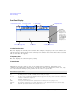
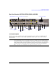
Rear Panel Overview (N5171B, N5172B, N5181B, & N5182B)
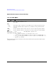
Rear Panel Overview (N5171B, N5172B, N5181B, & N5182B)
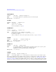
1. AC Power Receptacle
The AC power cord receptacle accepts a three–pronged AC power cord that is supplied with the
signal generator. For details on line setting requirements and the power cord, see the Getting
Started Guide.
CAUTION To avoid the loss of data, GPIB settings, or current user instrument states that have not
been permanently saved to non- volatile memory, the signal generator should always be
powered down either via the instrument’s front panel power button or the appropriate
SCPI command.
Signal generators installed in rack systems and powered down with the
system rack power switch rather than the instrument’s front panel switch display a
Error - 310 due to the instrument not being powered down correctly.
4. SWEEP OUT
2. EXT 1 &
EXT 2
5. PULSE
6. TRIG 1 & 2
7. REF IN
9. GPIB
10. LAN
11. Device USB
8. 10 MHz OUT
1. AC Power Receptacle
Option 1EM
only
See page 7
Digital Modulation Connectors (Vector Models Only) on page 16
12. Host USB
13. SD Card
3. LF OUT