
User`s guide


Agilent X-Series Signal Generators User’s Guide 257
Digital Signal Interface Module (Option 003/004)
Clock Timing
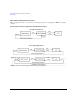
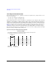
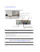
Figure 10-2 Clock Source Selection
When you select a clock source, you must let the N5102A module know the frequency of the clock
signal using the Clock Rate softkey. In the internal clock source mode, use this softkey to set the
internal clock rate. For device and external clock sources, this softkey must reflect the frequency of
the applied clock signal.
When the clock source is Internal, a frequency reference must be applied to the Freq Ref connector.
The frequency of this applied signal needs to be specified using the Reference Frequency softkey, unless
the current setting matches that of the applied signal.
The selected clock source provides the interface module output clock signal at the Clock Out and the
Device Interface connectors.
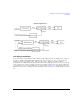
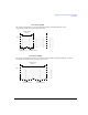
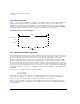
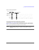
Common Frequency Reference
The clocking flexibility of the digital signal interface module allows the setting of arbitrary clock rates
for the device under test. In general, the clock rate inside the signal generator will be different from
the interface module clock rate, so the interface module performs a rate conversion. An important
aspect of this conversion is to have accurate clock rate information to avoid losing data. The module
relies on relative clock accuracy, instead of absolute accuracy, that must be ensured by using a single
frequency reference for all clock rates involved in the test setup. This can be implemented in various
ways (see the five drawings in
Figure 10- 3 on page 258), but whatever way it is implemented, the
clock inside the signal generator must have the same base frequency reference as the clock used by
the device under test.
Internal clock source
selection: Set the frequency of
the applied reference signal.
External and Device
selection:
Set to match the clock rate
of the applied clock signal
internal selection: Set the
internal clock rate.