
User`s guide


266 Agilent X-Series Signal Generators User’s Guide
Digital Signal Interface Module (Option 003/004)
Connecting the Clock Source and the Device Under Test
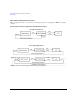
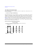
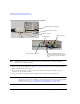
Figure 10-8 Example Setup using the Signal Generator 10 MHz Frequency Reference
NOTE You must disconnect the digital bus cable and the digital module while downloading
firmware to the signal generator.
1. Refer to the five setup diagrams in Figure 10- 3 on page 258 and connect the frequency reference
cable according to the clock source.
2. If an external clock source is used, connect the external clock signal to the Ext Clock In
connector on the interface module.
3. Select the break- out board that has the output connector suited for the application.
NOTE If the Device Interface mating connector is used with the device under test, refer to
Figure 10- 8 for the device interface connection and connect the device to the N5102A
module. Then proceed to “Operating the N5102A Module in Output Mode” on
page 269 or “Operating the N5102A Module in Input Mode” on page 280.
Signal generator 10 MHz Out
Freq Ref connector
Device interface connection
Device under test
Break-out board
User furnished ribbon cable(s) connect
between the device and break-out board.
Common Freq Ref cable
The clock to the device is in the ribbon
cable.