
User`s guide


Agilent X-Series Signal Generators User’s Guide 275
Digital Signal Interface Module (Option 003/004)
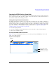
Operating the N5102A Module in Output Mode
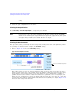
Figure 10-14 Clock Setup Menu Location
From this softkey menu, set all of the clock parameters that synchronize the clocks between the
N5102A module and the signal generator. You can also change the clock signal phase so the clock
occurs during the valid portion of the data. Figure 10- 15 shows the clock setup menu.
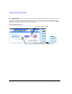
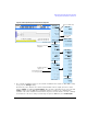
Figure 10-15 Clock Setup Softkey Menu for a Parallel Port Configuration
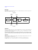
The top graphic on the display shows the current clock source that provides the output clock
signal at the Clock Out and Device Interface connectors. The graphic changes to reflect the clock
Accesses the
Clock Setup Menu
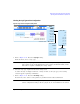
Inactive for a serial port configuration and the IF signal type
Active for only the Internal clock source selection
Inactive for clock rates below 25 MHz
Inactive for clock rates below
10 MHz and above 200 MHz