
User`s guide

276 Agilent X-Series Signal Generators User’s Guide
Digital Signal Interface Module (Option 003/004)
Operating the N5102A Module in Output Mode
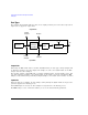
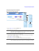
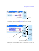
source selection discussed later in this procedure. The bottom graphic shows the clock position
relative to the data. The displayed clock signal will change to reflect the following:
• clocks per sample selection
• clock phase choice
• clock skew adjustment
• clock polarity selection
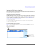
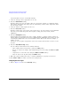
If the device or external clock does not match the frequency, one of the following error messages
will appear on the signal generator:
805 Digital module output FIFO overflow error; There are more samples being produced than
can be consumed at the current clock rate. Verify that the digital module clock is set up
properly.