
User`s guide

Agilent X-Series Signal Generators User’s Guide 285
Digital Signal Interface Module (Option 003/004)
Operating the N5102A Module in Input Mode
• clock polarity selection
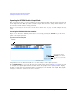
2. Press the Clock Source softkey.
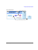
From this menu, select the clock signal source. With each selection, the clock routing display in
the signal generator clock setup menu will change to reflect the current clock source. This will be
indicated by a change in the graphic.
3. Select the clock source.
If External or Device is Selected
Press the Clock Rate softkey and enter the clock rate of the externally applied clock signal.
NOTE The clock phase and clock skew may need to be adjusted any time the clock rate
setting is changed. Refer to
“Clock Timing for Phase and Skew Adjustments” on
page 264.
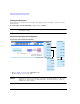
For the External selection, the signal is supplied by an external clock source and applied to the
Ext Clock In connector. For the Device selection, the clock signal is supplied through the Device
Interface connector, generally by the device being tested.
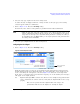
If Internal is Selected
Using an external frequency reference, the N5102A module generates its own internal clock signal.
The reference frequency signal must be applied to the Freq Ref connector on the digital module.
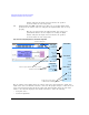
a. Press the Reference Frequency softkey and enter the frequency of the externally applied
frequency reference.
b. Press the Clock Rate softkey and enter the appropriate clock rate.
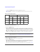
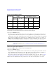
Table 10- 8 provides a quick view of the settings and connections associated with each clock
source selection.