
User`s guide

Agilent X-Series Signal Generators User’s Guide 295
BERT (Option UN7)
Bit Error Rate Tester–Option UN7
Clock Delay Function
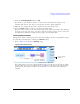
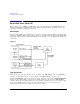
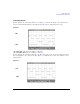
In this example, the clock delay function is off. Figure 11- 4 shows the input of the internal error
detector of UN7 through AUX I/O and indicates that the data is delayed from the clock.
Figure 11-4
CH1: BER TEST OUT (pin 17 of AUX I/O connector)
CH2: BER MEAS END (pin 15 of AUX I/O connector)
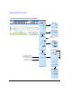
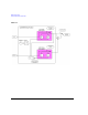
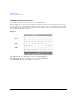
In this example, the clock delay function is on. The rising edge of the clock was delayed by 200 ns
and was adjusted to the center of the data.
Figure 11- 5 indicates the result of the using the clock
delay function.
Figure 11-5
CH1
CH2
CH1
CH2