
User`s guide

302 Agilent X-Series Signal Generators User’s Guide
BERT (Option UN7)
Bit Error Rate Tester–Option UN7
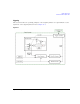
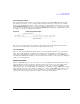
Figure 11-12 Repeat Measurements Example
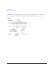
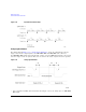
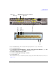
Testing Signal Definitions
The timing diagram Figure 11- 13, “Testing Signal Definitions,” shows the relationships between a
trigger event and the output signals at the BER MEAS END and BER TEST OUT connectors.
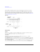
If a BER MEAS END signal stays high following a trigger event, the BERT measurement is in progress
and other trigger events are ignored. This state is stored in the status register and can be queried.
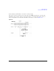
Figure 11-13 Testing Signal Definitions
• T1 is a firmware handling time measured from a Trigger event to the rising edge of a BER MEAS
END signal.