
User`s guide

304 Agilent X-Series Signal Generators User’s Guide
BERT (Option UN7)
Verifying BERT Operation
Verifying BERT Operation
The following procedures verify the operation of the signal generator’s bit error rate test (BERT)
function. The tests can be performed as part of a daily validation routine or can be used whenever
you want to check the validity of your BERT measurements. The procedures check the signal
generator’s BERT operation and do not ensure system performance to specifications.
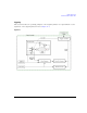
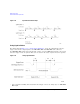
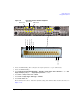
The highlighted BNC connectors in Figure 11- 14 are used for different signals in the BERT capability
mode. The BERT- specific configuration is shown here. The AUX I/O connector configuration is
customizable for the applications/options being used.
Figure 11- 14 shows the rear panel connectors
used for the BERT capability, and the configuration of the AUX I/O connector. For more information
about the AUX I/O connector, refer to
Rear Panel Overview (N5171B, N5172B, N5181B, & N5182B) on
page 13.
Measurement Setup Using Self-Test Mode
The following steps set up the signal generator for the BERT measurement selt- test.
1. Refer to Figure 11- 14 and make the following connections on the signal generator’s rear panel.
• DATA OUT (Aux I/O connector pin 15) to BER DATA IN (BNC connector labeled EVENT 1).
• DATA CLK OUT (Aux I/O connector pin 17) to BER CLK IN (BNC connector labeled BB
TRIG1).