
User`s guide

18 Agilent X-Series Signal Generators User’s Guide
Signal Generator Overview
Rear Panel Overview (N5171B, N5172B, N5181B, & N5182B)
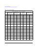
AUX I/O Connector
This female 36- pin connector is available only on instruments with an internal baseband generator
(Option 653, 655, 656, 657). On signal generators without one of these options, this connector is not
present.
The AUX I/O connector allows the X- Series signal generator to interface with external equipment by
sending and/or receiving supplementary (auxiliary) signaling information. This information is non- RF
related signaling such as:
• output markers to an external device from Arbitrary waveform playback sent to external
equipment to trigger or respond to waveform changes.
• output of signal markers to an external device from real- time signal generation personalities.
Signals such as frame markers, pulse- per- second, and even- second, for example, may be
supported, depending on the signal generation personality (CDMA, 3GPP, GNSS, LTE, etc.).
• input signals from external devices under test to cause the signal generator to modify
characteristics of a signal being generated, depending on the signal generation personality (CDMA,
3GPP, LTE, etc.).
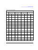
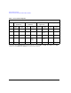
Table 1- 1 on page 20 describes the inputs and outputs accessible through the AUX I/O connector.
The specific functions controllable by auxiliary signaling vary significantly from one real- time signal
generation personality to another. Refer to the documentation for each real- time signal generation
personality for additional information.
NOTE The AUX I/O connector supports standard 3.3V TTL signaling levels. Signals support data
rates up to 50 MHz with minimum rise and fall times of 3ns. Any pins that are not
connected will have a weak pull- up to 3.3V.
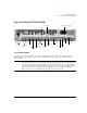
18
1
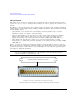
19
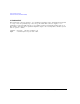
36
The AUX I/O connector is a shielded .050 series board mount connector.
View looking into the rear panel female 36–pin connector
The AUX I/O mating connector manufacturer’s part number is 3M® 10136-3000 (wire mount plug).