
User`s guide

22 Agilent X-Series Signal Generators User’s Guide
Signal Generator Overview
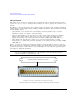
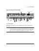
Rear Panel Overview (N5171B, N5172B, N5181B, & N5182B)
32
GND GND GND GND GND GND
33
Data Out AUX
Out(1)
34
GND GND GND GND GND GND
35
Symbol
Sync
Output
AUX
Out(2)
36
GND GND GND GND GND GND
a
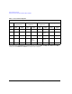
Settings shown are for the Error Out signal configuration of the AUX I/O connector (BERT > I/O Setup > Aux I/O Out). Press the Help
hardkey, then either Reference Out or PN9 Out for the respective signal configuration.
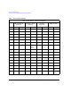
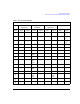
Table 1-1 AUX I/O Connector Configuration
MXG and EXG AUX I/O Connector Configuration
ARB & ARB- Based
Applications
Real- Time Custom
Modulation
Real- Time
Applications
BERT Capability
Pin # Input Output Input Output Input Output Input Output