
User`s guide

348 Agilent X-Series Signal Generators User’s Guide
Custom Digital Modulation (Option 431)
Using the Arbitrary Waveform Generator
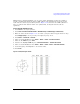
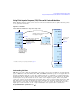
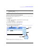
Figure 13- 26 shows the X- Series setup and the I/Q display.
Figure 13-26 Custom Modulation and I/Q Display
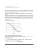
Hints for Constructing Modulations
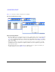
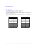
• The map is limited to 16 total signal levels for I and Q combined. The readout on the right- hand
side of the table tracks the number of I and Q levels utilized. Levels are I or Q values. Figure
13- 27 shows an 8PSK signal built in two different ways. The 8PSK signal in Figure 13- 27 utilizes
five of the available sixteen I/Q values on the left, and utilizes four of the available sixteen I/Q
values on the right.
• Following this example, the real- time I/Q baseband generator supports a symmetric 256QAM
constellation but not an asymmetric 256QAM constellation, since the asymmetry requires more
than sixteen I/Q values.
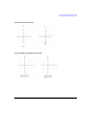
• The levels do not have to be equally spaced or symmetric in the I/Q plane. For example, the
16QAM modulations shown in Figure 13- 28 are both possible.