
User`s guide

Agilent X-Series Signal Generators User’s Guide 353
Custom Digital Modulation (Option 431)
Using Finite Impulse Response (FIR) Filters with Custom Modulation
Using Finite Impulse Response (FIR) Filters with Custom Modulation
Finite Impulse Response filters can be used to refine the transitions between symbol decision points
of the generated waveforms.
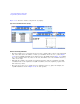
Figure 13-31 Filter Menu
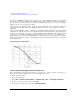
Understanding FIR Filters
FIR filters are used to limit the bandwidth of the input to the I and Q modulators. Several different
types of FIR filters exist. The NADC, PDC, PHS, and TETRA standards specify a root Nyquist filter in
both the transmitter and the receiver. The combined response is equivalent to a Nyquist filter. The
Nyquist filter has an impulse response that rings at the data clock rate so nulls appear at all symbol
decision points except the desired one at the center of the impulse response. Since each symbol
causes zero response at all undesired decision points, there can be no inter- symbol interference (ISI).
The alpha term (α) defined for Nyquist- type filters identifies the frequency cutoff point were the
filter response is zero. The closer the alpha term is to zero, the steeper the filter roll- off becomes.
Alpha gives a direct measure of the occupied bandwidth of the system and is calculated as
Occupied Bandwidth = Symbol Rate x (1 + α)
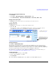
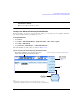
Mode > ARB Custom Modulation > Single Carrier Setup > Filter
This replaces the
current FIR filter with
the factory installed
default filter settings
for the current
modulation type.
This softkey changes, depending
on the selected filter–type.
Available only when the filter selected =
Root Nyquist or Nyquist
Available only when the
filter selected = Gaussian
page 359
Only applies to Dual
ARB Modulation. Refer
to page 145.
For details on each key, use key help as described on page 44.
Opens the IS–95
filter selection
menu.
page 355