Agilent Technologies Signal Generators E4428C/38C ESG RF E8663B/E8663D PSG RF Analog N5161A/62A/81A/82A MXG RF E8257D/67D PSG Microwave N5183A MXG Microwave Programming Guide (With Remote Operation and File Downloads) Agilent Technologies
Notices © Agilent Technologies, Inc. 2006 - 2010 Warranty No part of this manual may be reproduced in any form or by any means (including electronic storage and retrieval or translation into a foreign language) without prior agreement and written consent from Agilent Technologies, Inc. as governed by United States and international copyright laws. The material contained in this document is provided “as is,” and is subject to being changed, without notice, in future editions.
Contents 1 Getting Started with Remote Operation Programming and Software/Hardware Layers. . . . . . . . . . . . . . . . . . . . . . . . . . . . . . . . . . .2 Interfaces . . . . . . . . . . . . . . . . . . . . . . . . . . . . . . . . . . . . . . . . . . . . . . . . . . . . . . . . . .3 IO Libraries and Programming Languages . . . . . . . . . . . . . . . Agilent IO Libraries Suite . . . . . . . . . . . . . . . . . . . . . .
Contents Using Telnet LAN . . . . . . . . . . . . . . . . . . . . . . . . . . . . . . . . . . . . . . . . . . . . . . . . 44 Using FTP . . . . . . . . . . . . . . . . . . . . . . . . . . . . . . . . . . . . . . . . . . . . . . . . . . . . . 48 Using LXI . . . . . . . . . . . . . . . . . . . . . . . . . . . . . . . . . . . . . . . . . . . . . . . . . . . . . . 50 Using RS–232 (ESG and PSG Only) . . Selecting IO Libraries for RS–232 Setting Up the RS–232 Interface . Verifying RS–232 Functionality . .
Contents Queries for GPIB Using VISA and C . . . . . . . . . . . . . . . . . . . . . . . . . . . Generating a CW Signal Using VISA and C . . . . . . . . . . . . . . . . . . . . . . . Generating an Externally Applied AC- Coupled FM Signal Using VISA and C . Generating an Internal FM Signal Using VISA and C. . . . . . . . . . . . . . . . . Generating a Step- Swept Signal Using VISA and C++ . . . . . . . . . . . . . . . . Generating a Swept Signal Using VISA and Visual C++ . . . . . . . . . . . . . . .
Contents Standard Event Status Group . . . . . . . . . . Standard Operation Status Group . . . . . . . Baseband Operation Status Group . . . . . . . Data Questionable Status Group . . . . . . . . Data Questionable Power Status Group . . . Data Questionable Frequency Status Group. Data Questionable Modulation Status Group Data Questionable Calibration Status Group Data Questionable BERT Status Group . . . . 5 . . . . . . . . . . . . . . . . . . . . . . . . . . . . . . . . . . . . . . . . . . . . . . .
Contents Downloading Waveform Data . . . . . . . . . . . . . . . . . . . . . . . . . . . . . . . . . . . . . . . . . . . 241 Using Simulation Software . . . . . . . . . . . . . . . . . . . . . . . . . . . . . . . . . . . . . . . . . . 242 Using Advanced Programming Languages . . . . . . . . . . . . . . . . . . . . . . . . . . . . . . . . 244 Loading, Playing, and Verifying a Downloaded Waveform . Loading a File from Non–Volatile Memory. . . . . . . . Playing the Waveform . . . . . . . . . . . . . . . . . .
Contents Understanding Framed Transmission For Real–Time TDMA . . . . . . . . . . . . . . . . . . . . 333 Real–Time Custom High Data Rates. . . . . . . . . . . . . . . . . . . . . . . . . . . . . . . . . . . . 337 Pattern RAM (PRAM) Data Downloads (E4438C and E8267D) . . Understanding PRAM Files . . . . . . . . . . . . . . . . . . . . . . PRAM File Size . . . . . . . . . . . . . . . . . . . . . . . . . . . . . . SCPI Command for a List Format Download . . . . . . . . . . .
1 Getting Started with Remote Operation CAUTION NOTE Agilent does not recommend going backwards in firmware versions (loading older firmware versions into newer instruments) as hardware/firmware conflicts can result. For the N5161A/62A, the softkey menus and features mentioned in this chapter are only available through the Web- Enabled MXG or through SCPI commands. Refer to “Using the Web Browser” on page 11 and to the SCPI Command Reference.
Getting Started with Remote Operation Programming and Software/Hardware Layers Programming and Software/Hardware Layers Agilent MXG, ESG, PSG signal generators support the following interfaces: Instrument Interfaces Supported Agilent MXG GPIB, LAN, and USB 2.0 Agilent PSGa GPIB, LAN, and ANSI/EIA232 (RS- 232) serial connection Agilent ESG GPIB, LAN, and ANSI/EIA232 (RS- 232) serial connection a.
Getting Started with Remote Operation Interfaces Interfaces GPIB GPIB is used extensively when a dedicated computer is available for remote control of each instrument or system. Data transfer is fast because GPIB handles information in bytes with data transfer rates of up to 8 MBps. GPIB is physically restricted by the location and distance between the instrument/system and the computer; cables are limited to an average length of two meters per device with a total length of 20 meters.
Getting Started with Remote Operation IO Libraries and Programming Languages RS- 232b (ESG/PSG/E8663B Only) RS- 232 is an older method used to communicate with a single instrument; its primary use is to control printers and external disk drives, and connect to a modem. Communication over RS- 232 is much slower than with GPIB, USB, or LAN because data is sent and received one bit at a time. It also requires that certain parameters, such as baud rate, be matched on both the computer and signal generator.
Getting Started with Remote Operation IO Libraries and Programming Languages CAUTION NOTE For long strings of commands and waveform downloads, upgrading to Agilent IO Libraries 15.0 and above can decrease RS- 232 performance, potentially resulting in an Error –310. To learn about using IO libraries with Windows XP or newer operating systems, refer to the Agilent IO Libraries Suite’s help located on the Automation- Ready CD that ships with your signal generator.
Getting Started with Remote Operation IO Libraries and Programming Languages instructions in the setup wizard to install the libraries. NOTE Before setting the LAN interface, the signal generator must be configured for VXI- 11 SCPI. Refer to “Configuring the VXI–11 for LAN (Agilent MXG)” on page 32 or “Configuring the VXI–11 for LAN (ESG/PSG)” on page 33. Refer to the Agilent IO Libraries Suite Help documentation for details about this software.
Getting Started with Remote Operation IO Libraries and Programming Languages Using VISA Configuration (Manual) Use the Agilent IO Libraries Suite 15.0, to perform the following steps to use the Connection Expert and VISA to manually configure an interface. 1. Run the Agilent Connection Expert program: Start > All Programs > Agilent IO Libraries Suite > Agilent Connection Expert >. 2. On the tool bar select the Add Interface button. 3. Click LAN Interface in the Available interface types text box. 4.
Getting Started with Remote Operation IO Libraries and Programming Languages Windows NT and Agilent IO Libraries M (and Earlier) NOTE Windows NT is not supported on Agilent IO Libraries 14.0 and newer. The following sections are specific to Agilent IO Libraries versions M and earlier and apply only to the Windows NT platform. For additional information on older versions of Agilent IO libraries, refer to the Agilent Connection Expert in the Agilent IO Libraries Help.
Getting Started with Remote Operation IO Libraries and Programming Languages VISA Configuration (Automatic) 1. Run the VISA Assistant program. 2. Click on the interface you want to use for sending commands to the signal generator. 3. Click the Formatted I/O tab. 4. Select SCPI in the Instr. Lang. section. You can enter SCPI commands in the text box and send the command using the viPrintf button.
Getting Started with Remote Operation IO Libraries and Programming Languages Selecting IO Libraries for GPIB The IO libraries are included with the GPIB interface card, and can be downloaded from the National Instruments website or the Agilent website. See also, “IO Libraries and Programming Languages” on page 4 for information on IO libraries. The following is a discussion on these libraries.
Getting Started with Remote Operation Using the Web Browser Programming Languages Along with Standard Commands for Programming Instructions (SCPI) and IO library functions, you use a programming language to remotely control the signal generator. Common programming languages include: • • • • • • • • • C/C++ C# MATLAB® (MATLAB is a registered trademark of The MathWorks.) HP Basic LabView Java™ (Java is a U.S. trademark of Sun Microsystems, Inc.
Getting Started with Remote Operation Using the Web Browser The instrument can be accessed through a standard web browser, when it is connected to the LAN. To access through the web browser, enter the instrument IP address or the hostname as the URL in your browser.
Getting Started with Remote Operation Using the Web Browser Modifying the Signal Generator Configuration NOTE Use Help with this Page for assistance with the Web- Enabled interface. 1. From the welcome page of the Web- Enabled interface, click View & Modify Configuration to show the instrument’s currently assigned IP address and other parameters. 2. Enter the new settings and click Save. 3. Click Renew LAN Settings to cause the new settings to take effect.
Getting Started with Remote Operation Using the Web Browser Enabling the Signal Generator Web Server NOTE Javascript or Active Scripts must be enabled to use the web front panel controls. 1. Turn on the Web server as shown below. Agilent MXG Web Server On If necessary, toggle Web Server to On. For details on each key, use the key help. Refer to “Getting Help (Agilent MXG)” on page 20 and the User’s Guide. For additional SCPI command information, refer to the SCPI Command Reference.
Getting Started with Remote Operation Using the Web Browser 3. In the web browser address field, enter the signal generator’s IP address. For example, http://101.101.101.101 (where 101.101.101.101 is the signal generator’s IP address). The IP (internet protocol) address can change depending on the LAN configuration (see “Using LAN” on page 31). 4. On the computer’s keyboard, press Enter. The web browser displays the signal generator’s homepage. 5.
Getting Started with Remote Operation Using the Web Browser FTP enables the transfer of files between the instrument and a computer. The FTP access button provides drag- and- drop file capability. The FTP access softkey opens to show the folders containing the signal generator’s memory catalog files. Use the FTP window to drag and drop files from the FTP page to your computer.
Getting Started with Remote Operation Using the Web Browser LAN Configuration System Defaults (Agilent MXG) NOTE The instrument’s LAN configuration system information can be found on the signal generator’s homepage and on the signal generator. Refer to “Enabling the Signal Generator Web Server” on page 14 and to “Displaying the LAN Configuration Summary (Agilent MXG)” on page 18.
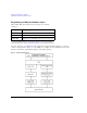
Getting Started with Remote Operation Using the Web Browser Table 1-1 LAN Configuration Summary Values Parameter Default TCP Keep Alive: On Domain Name:a TCP Keep Alive Timeout: 1800.0 sec Signal Generator Web Server Interface Description: Agilent () SICL Interface Nameb: gpib0 Web Password: agilent a.The Domain Name defaults to a null field. b.
Getting Started with Remote Operation Preferences Preferences The following commonly- used manual command sections are included here: “Configuring the Display for Remote Command Setups (Agilent MXG)” on page 19 “Configuring the Display for Remote Command Setups (ESG/PSG)” on page 20 “Getting Help (Agilent MXG)” on page 20 “Setting the Help Mode (ESG/PSG)” on page 21 “Setting the Help Mode (ESG/PSG)” on page 21 Configuring the Display for Remote Command Setups (Agilent MXG) Select Update in Remote until O
Getting Started with Remote Operation Preferences Configuring the Display for Remote Command Setups (ESG/PSG) SCPI commands: :DISPlay:REMote ON|OFF|1|0 :DISPlay:REMote? Select Update in Remote until On is highlighted. Using the Update in Remote softkey updates the display but not the softkeys on each SCPI command. In general, the softkeys are not updated until the SCPI command SYST:DISP:GTL is sent. For details on each key, use the Key and Data Field Reference.
Getting Started with Remote Operation Preferences Setting the Help Mode (ESG/PSG) SCPI commands: :SYSTem:HELP:MODE SINGle|CONTinuous :SYSTem:HELP:MODE? When you press Help: Single: Help displays only for the next key you press. Cont: Help displays for each key you press and that key’s function activates. To turn off the function, press Help. For details on each key, use the Key and Data Field Reference. For additional SCPI command information, refer to the SCPI Command Reference.
Getting Started with Remote Operation Troubleshooting Troubleshooting In each section of this document, there is information that is related to troubleshooting that topic, if applicable. Refer to those corresponding sections in this document as well as to the User’s Guide, before using the diagnostics mode referred to in the Service Guide and in the caution below.
Getting Started with Remote Operation Error Messages Error Messages If an error condition occurs in the signal generator, it is reported to both the SCPI (remote interface) error queue and the front panel display error queue. These two queues are viewed and managed separately; for information on the front panel display error queue, refer to the User’s Guide.
Getting Started with Remote Operation Error Messages Error Message Types Events generate only one type of error. For example, an event that generates a query error will not generate a device- specific, execution, or command error. Query Errors (–499 to –400) indicate that the instrument’s output queue control has detected a problem with the message exchange protocol described in IEEE 488.2, Chapter 6. Errors in this class set the query error bit (bit 2) in the event status register (IEEE 488.2, section 11.
2 Using IO Interfaces NOTE For the N5161A/62A the softkey menus and features mentioned in this chapter are only available through the Web–Enabled MXG or through SCPI commands. Refer to “Using the Web Browser” on page 11 and to the SCPI Command Reference.
Using IO Interfaces Using GPIB Interface Type Operating System IO Library Languages Backplane/ BUS Max IO (kB/sec) Buffering Agilent USB/GPIB Interface Converter for PC–Based Systems Agilent 82357A Converter Windowsa 98(SE)/ME/ 2000®/XP VISA / SICL C/C++, Visual Basic, Agilent VEE, HP Basic for Windows, NI Labview USB 2.0 (1.
Using IO Interfaces Using GPIB Interface Type Operating System IO Library Languages Backplane/ BUS Max IO (kB/sec) Buffering Agilent USB/GPIB Interface Converter for PC–Based Systems Agilent E2078A HP–UX 10.20 VISA/SICL ANSI C, Agilent VEE, Agilent BASIC, HP–UX PCI 750 Built–in a.Windows 95, 98(SE), NT, 2000, and XP are registered trademarks of Microsoft Corporation. b.Windows 98 and ME are registered trademarks of Microsoft Corporation. c.NI–488.
Using IO Interfaces Using GPIB Figure 2-2 Setting the GPIB Address on the ESG/PSG SCPI commands: :SYSTem:COMMunicate:GPIB:ADDRess :SYSTem:COMMunicate:GPIB:ADDRess? Default address: 19 Range: 0–30 For details on each key, use the Key and Data Field Reference. For additional SCPI command information, refer to the SCPI Command Reference. Connect a GPIB interface cable between the signal generator and the computer. (The following table lists cable part numbers.
Using IO Interfaces GPIB Programming Interface Examples GPIB Interface Terms An instrument that is part of a GPIB network is categorized as a listener, talker, or controller, depending on its current function in the network. listener A listener is a device capable of receiving data or commands from other instruments. Several instruments in the GPIB network can be listeners simultaneously. talker A talker is a device capable of transmitting data.
Using IO Interfaces GPIB Programming Interface Examples 170 LOCAL Sig_gen ! Places the signal generator into Local mode 180 CLEAR Sig_gen ! Clears any pending data I/O and resets the parser 190 REMOTE 719 ! Puts the signal generator into remote mode 200 CLEAR SCREEN ! Clears the controllers display 210 REMOTE 719 220 OUTPUT Sig_gen;"*RST" ! Places the signal generator into a defined state Interface Check Using NI–488.
Using IO Interfaces Using LAN Using LAN The Agilent MXG is capable of 100Base–T LAN communication. The ESG, PSG, and E8663B are designed to connect with a 10Base–T LAN. Where auto–negotiation is present, the ESG, PSG, and E8663B can connect to a 100Base–T LAN, but communicate at 10Base–T speeds. For more information refer to http://www.ieee.org.
Using IO Interfaces Using LAN Setting Up the LAN Interface For LAN operation, the signal generator must be connected to the LAN, and an IP address must be assigned to the signal generator either manually or by using DHCP client service. Your system administrator can tell you which method to use. (Most modern LAN networks use DHCP.) NOTE Verify that the signal generator is connected to the LAN using a 100Base–T LAN or 10Base–T LAN cable.
Using IO Interfaces Using LAN Configuring the VXI–11 for LAN (ESG/PSG) Utility > GPIB/RS–232 LAN For details on each key, use the Key and Data Field Reference. For additional SCPI command information, refer to the SCPI Command Reference. NOTE To communicate with the signal generator over the LAN, you must enable the VXI–11 SCPI service. Select VXI–11 until On is highlighted. (Default condition is On.) Use a 10Base–T LAN cable to connect the signal generator to the LAN.
Using IO Interfaces Using LAN Manually Configuring the Agilent MXG LAN Utility > IO Config Your hostname can be up to 20 characters long. SCPI commands: :SYSTem:COMMunicate:LAN:CONFig MANual :SYSTem:COMMunicate:LAN:CONFig? For details on each key, use the key help (described in User’s Guide). For additional SCPI command information, refer to the SCPI Command Reference.
Using IO Interfaces Using LAN DHCP Configuration If the DHCP server uses dynamic DNS to link the hostname with the assigned IP address, the hostname may be used in place of the IP address. Otherwise, the hostname is not usable. For more information on the DHCP configuration, refer to “Configuring the DHCP LAN (Agilent MXG)” on page 35 or “Configuring the DHCP LAN (ESG/PSG)” on page 36.
Using IO Interfaces Using LAN Configuring the DHCP LAN (ESG/PSG) NOTE Use a 10Base–T LAN cable to connect the signal generator to the LAN. For details on each key, refer to the Key and Data Field Reference. For additional SCPI command information, refer to the SCPI Command Reference. DHCP: Request a new IP address from the DHCP server each power cycle. Confirming this action configures the signal generator as a DHCP client.
Using IO Interfaces Using LAN From a UNIX® workstation, type (UNIX is a registered trademark of the Open Group): ping 64 10 where is your instrument’s name or IP address, 64 is the packet size, and 10 is the number of packets transmitted. Type man ping at the UNIX prompt for details on the ping command.
Using IO Interfaces Using LAN instrument will use the default IP address value and the others will have randomly chosen IP address values. If you have not manually set the IP addresses of your N5161A/62A instruments (and you need to know the addresses), turn each N5161A/62A instrument on one at a time to set the default IP address. Then manually configure the IP address of each instrument using the Web- Enabled interface as described in “Using the Web Browser” on page 11.
Using IO Interfaces Using LAN NOTE The following sections are specific to Agilent IO Libraries versions M and earlier and apply only to the Windows NT platform.
Using IO Interfaces Using LAN Using VISA Assistant Use the VISA Assistant, available with the Agilent IO Library versions M and earlier, to communicate with the signal generator over the LAN interface. However, you must manually configure the VISA LAN client. Refer to the Help menu for instructions on configuring and running the VISA Assistant program. 1. Run the IO Config program. 2. Click on TCPIP0 in the Available Interface Types text box. 3. Click the Configure button.
Using IO Interfaces Using LAN Figure 2-3 IO Config Form (Windows NT) Check to see that the Default Protocol is set to Automatic. 1. Run the IO Config program. 2. Click on TCPIP in the Configured Interfaces text box. If there is no TCPIP0 in the box, follow the steps shown in the section “Using VISA Assistant” on page 40. 3. Click the Edit button. 4. Click the radio button for AUTO (automatically detect protocol). 5. Click OK, OK to end the IO Config program.
Using IO Interfaces Using LAN Using VXI–11 The signal generator supports the LAN interface protocol described in the VXI–11 standard. VXI–11 is an instrument control protocol based on Open Network Computing/Remote Procedure Call (ONC/RPC) interfaces running over TCP/IP. It is intended to provide GPIB capabilities such as SRQ (Service Request), status byte reading, and DCAS (Device Clear State) over a LAN interface.
Using IO Interfaces Using LAN Figure 2-4 Show Devices Form (Agilent IO Library version J.01.0100) Using Sockets LAN NOTE Users with Windows XP operating systems and newer can use this section to better understand how to use the signal generator with port settings. For more information, refer to the help software of the IO libraries being used. Sockets LAN is a method used to communicate with the signal generator over the LAN interface using the Transmission Control Protocol/Internet Protocol (TCP/IP).
Using IO Interfaces Using LAN Before you can use sockets LAN, you must select the signal generator’s sockets port number to use: • Standard mode. Available on port 5025. Use this port for simple programming. • TELNET mode. The telnet SCPI service is available on port 5023. NOTE For backward compatibility, on the E8663B, ESG, and PSG, the signal generator also accepts references to the Telnet SCPI service at port 7777 and sockets SCPI service at port 7778.
Using IO Interfaces Using LAN 2. At the command prompt, type in telnet. 3. Press the Enter key. The Telnet display screen will be displayed. 4. Click on the Connect menu then select Remote System. A connection form (Figure 2- 5) is displayed. Figure 2-5 Connect Form (Agilent IO Library version J.01.0100) 5. Enter the hostname, port number, and TermType then click Connect. • Host Name−IP address or hostname • Port−5023 • Term Type−vt100 6. At the SCPI> prompt, enter SCPI commands.
Using IO Interfaces Using LAN Figure 2-6 Telnet Window (Windows 2000) Using Telnet On Windows 2000 1. On your PC, click Start > Run. 2. Type telnet in the run text box, then click the OK button. The Telnet connection screen will be displayed. See Figure 2- 7 on page 47 (Windows 2000). 3. Type open at the prompt and then press the Enter key. The prompt will change to (to). 4.
Using IO Interfaces Using LAN Figure 2-7 Telnet 2000 Window The Standard UNIX Telnet Command Synopsis telnet [host [port]] Description This command is used to communicate with another host using the Telnet protocol. When the command telnet is invoked with host or port arguments, a connection is opened to the host, and input is sent from the user to the host. Options and Parameters The command telnet operates in character–at–a–time or line–by–line mode.
Using IO Interfaces Using LAN Unix Telnet Example To connect to the instrument with host name myInstrument and port number 5023, enter the following command on the command line: telnet myInstrument 5023. When you connect to the signal generator, the UNIX window will display a welcome message and a SCPI command prompt. The instrument is now ready to accept your SCPI commands. As you type SCPI commands, query results appear on the next line.
Using IO Interfaces Using LAN Figure 2-8 FTP Screen The following steps outline a sample FTP session from the MS–DOS Command Prompt: 1. On the PC click Start > Programs > Command Prompt. 2. At the command prompt enter: ftp < IP address > or < hostname > 3. At the user name prompt, press enter. 4. At the password prompt, press enter. You are now in the signal generator’s user directory. Typing help at the command prompt will show you the FTP commands that are available on your system. 5.
Using IO Interfaces Using LAN Using LXI NOTE Full LXI–B feature implementation is only available on instruments with firmware >A.01.50. A license may be required to enable this feature and to download firmware versions >A.01.50. For information on new firmware releases, go to http://www.agilent.com/find/upgradeassistant.
Using IO Interfaces Using LAN Verifying Time Synchronization To verify that both instruments are running PTP, open the Interactive LXI tool from a PC which is connected to the same switch as the MXA and MXG. This program is bundled with the Agilent IO Libraries Suite. 1. Open Interactive LXI. From a PC connected to the same subnet as the instrument go to: Start > All Programs > Agilent IO Libraries Suite > Utilities > Interactive LXI. 2. Open the Timing menu. Click on the tab labeled Timing. 3.
Using IO Interfaces Using LAN Peer to Peer Messaging The MXA and MXG are capable of sending and receiving LXI specific LAN packets. The packets are configurable, and may be sent when various instrument events occur during a measurement or state recall. Each instrument event has an associated sense of 0 or 1 to indicate whether or not the event is active. The instrument events that can cause an MXG to send an LXI LAN packet are summarized in the table below.
Using IO Interfaces Using LAN Using the Front Panel to Configure LXI Events The MXG can be configured to send output LAN events for the pre–defined LXI events through the front panel softkeys. 1. Press Utility > More > LXI–B > Configure LXI Events > Configure LXI Output Events 2. From the Output Events menu: Press Select Source. Choose the instrument status event to be used as a source for the output LAN event. 3. Press Toggle Event State to enable the highlighted output LAN event.
Using IO Interfaces Using LAN Using the front panel to configure an LXI Trigger on the MXG The MXG is capable of reacting to an incoming LXI LAN Event by treating it as a trigger. The following procedure describes how to set up the MXG sweep trigger to use an LXI event through the front panel soft keys. 1. Select the LXI LAN trigger as the source for sweep triggers. Press Sweep > More > Sweep Trigger > More > LXI LAN 2. Select a Trigger LAN Event.
Using IO Interfaces Using LAN 4. Monitor Response as on page 53. This may be done assuming that the Output LAN event had been configured from the front panel (page 52) or SCPI commands (page 53). Using the LXI Event Log The LXI subsystem also provides an Event Log. The event log records all of the enabled LXI Event and Instrument Event activity and associates each action with an IEEE 1588 timestamp. Instrument Events are enabled by default, and will therefore appear in the log.
Using IO Interfaces Using LAN The MXA receives the LAN0 event and triggers. The MXA's Waiting For Trigger instrument event transitions low, and a LAN1 output event goes onto the LAN with a falling edge. The MXG takes no action, since it is configured to trigger only on rising edges. The MXA completes its measurement and prepares to move on to the next frequency in its list. The MXA's Waiting For Trigger instrument event transitions high, and a LAN1 output event goes onto the LAN with a rising edge.
Using IO Interfaces Using LAN 8. Sets the MXG how the lists will be entered: Send the following SCPI command: :LIST:TYPE LIST An arbitrary list will be used instead of range and step size arguments. 9. Send the MXG a list of frequencies: Send the following SCPI command: :LIST:FREQ 100MHz,200MHz,300MHz,400MHz,500MHz The MXG will put out signals at these frequencies and in this order. 10.
Using IO Interfaces Using LAN 17. Disable LXI Output LAN Events on the MXA: Send the following SCPI command: :LXI:EVENt:OUTPut:LAN:DISable:ALL 18. Put the MXA into SA mode: Send the following SCPI command: :INST:SEL SA 19. Put the MXA into single sweep mode: Send the following SCPI command: :INIT:CONT OFF 20. Choose the MXA's PTP domain: Send the following SCPI command: :LXI:CLOCk:PTP:DOMain 0 The parameter value should match the one used in step 3. 21.
Using IO Interfaces Using LAN 25. Make sure the MXA's LXI LAN triggers are disabled: Send the following SCPI command: :TRIG:LXI:LAN:DISable:ALL 26. Set the MXA's trigger source to LXI LAN: Send the following SCPI command: :LIST:TRIG:SOUR LAN 27.
Using IO Interfaces Using LAN 33. Send the MXG a "LAN1" peer to peer message: Using Interactive LXI or the Agilent IO Libraries TMFramework LXI library: send a "LAN1" peer to peer message to the MXG. This will start the synchronization sequence. 34. The MXA waits for the "OperationComplete" instrument event: Detect the peer to peer traffic using Interactive LXI. To programmatically listen for LXI peer to peer messages, use the Agilent IO Libraries TMFramework LXI library.
Using IO Interfaces Using RS–232 (ESG and PSG Only) For More Information For more information on using LXI see the Agilent website dedicated to LXI instrumentation: www.agilent.com/find/lxi.
Using IO Interfaces Using RS–232 (ESG and PSG Only) The following sections contain information on selecting and connecting IO libraries and RS–232 interface hardware on the signal generator to a computer’s RS–232 connector. • “Selecting IO Libraries for RS–232” on page 62 • “Setting Up the RS–232 Interface” on page 63 • “Verifying RS–232 Functionality” on page 65 Selecting IO Libraries for RS–232 The IO libraries can be downloaded from the National Instrument website, http://www.ni.
Using IO Interfaces Using RS–232 (ESG and PSG Only) Setting Up the RS–232 Interface 1. Setting the RS–232 Interface Baud Rate (ESG/PSG/E8663B) Select a baud rate of 9600. SCPI commands: :SYSTem:COMMunicate:SERial:BAUD :SYSTem:COMMunicate:SERial:BAUD? For details on each key, use the key help (described in User’s Guide). For additional SCPI command information, refer to the SCPI Command Reference. NOTE Configure your computer to use baud rates 57600 or lower only.
Using IO Interfaces Using RS–232 (ESG and PSG Only) 2. Setting the RS–232 Echo Softkey Toggle RS–232 Echo Off On until Off is highlighted. Selecting On echoes or returns characters sent to the signal generator and prints them to the display. SCPI commands: :SYSTem:COMMunicate:SERial:ECHO ON|OFF :SYSTem:COMMunicate:SERial:ECHO? For details on each key, use the key help (described in User’s Guide). For additional SCPI command information, refer to the SCPI Command Reference. 3.
Using IO Interfaces Using RS–232 (ESG and PSG Only) Verifying RS–232 Functionality You can use the HyperTerminal program available on your computer to verify the RS–232 interface functionality. To run the HyperTerminal program, connect the RS–232 cable between the computer and the signal generator and perform the following steps: 1. On the PC click Start > Programs > Accessories > Communications > HyperTerminal. 2. Select HyperTerminal. 3. Enter a name for the session in the text box and select an icon. 4.
Using IO Interfaces RS–232 Programming Interface Examples Character Format Parameters The signal generator uses the following character format parameters when communicating through RS–232: • Character Length: Eight data bits are used for each character, excluding start, stop, and parity bits. • Parity Enable: Parity is disabled (absent) for each character. • Stop Bits: One stop bit is included with each character. If You Have Problems 1.
Using IO Interfaces RS–232 Programming Interface Examples Interface Check Using HP BASIC This portion of the example program “Interface Check Using HP BASIC” on page 67, causes the signal generator to perform an instrument reset. The SCPI command *RST will place the signal generator into a pre–defined state. The serial interface address for the signal generator in this example is 9. The serial port used is COM1 (Serial A on some computers).
Using IO Interfaces RS–232 Programming Interface Examples Queries Using HP Basic and RS–232 This portion of the example program “Queries Using HP Basic and RS–232” on page 68, example program demonstrates signal generator query commands over RS–232. Query commands are of the type *IDN? and are identified by the question mark that follows the mnemonic.
Using IO Interfaces Using USB (Agilent MXG) Using USB (Agilent MXG) CAUTION USB cables are not industrial graded and potentially allows data loss in noisy environments. USB cables do not have a latching mechanism and the cables can be pulled out of the PC or instrument relatively easily. The maximum length for USB cables is 30 m, including the use of inline repeaters. NOTE The USB interface is available only on the Agilent MXG signal generator. The Agilent MXG’s USB 2.
Using IO Interfaces Using USB (Agilent MXG) Selecting I/O Libraries for USB CAUTION The Agilent MXG’s USB interface requires Agilent IO Libraries Suite 14.1 or newer to run properly. For more information on connecting instruments to the USB, refer to the Agilent Connection Expert in the Agilent IO Libraries Help. The I/O libraries can be downloaded from the National Instrument website, http://www.ni.com, or Agilent’s website, http://www.agilent.com. The following is a discussion on these libraries.
Using IO Interfaces Using USB (Agilent MXG) Front Panel USB (Type–A) For details on using the front panel USB (Type–A) and the front panel USB Media operation, refer to the User’s Guide. Verifying USB Functionality Mini–B 5 Pin Rear Panel Connector NOTE For information on verifying your Mini–B 5 pin USB (rear panel) functionality, refer to the Agilent Connection Expert in the Agilent IO Libraries Help.
Using IO Interfaces Using USB (Agilent MXG) 72 Agilent Signal Generators Programming Guide
3 Programming Examples NOTE For the N5161A/62A the softkey menus and features mentioned in this chapter are only available through the Web- Enabled MXG or through SCPI commands. Refer to “Using the Web Browser” on page 11 and to the SCPI Command Reference.
Programming Examples Using the Programming Interface Examples Update in Remote function. (For more information, refer to or “Configuring the Display for Remote Command Setups (Agilent MXG)” on page 19.) or “Configuring the Display for Remote Command Setups (ESG/PSG)” on page 20.
Programming Examples Using the Programming Interface Examples C/C++ Examples • “Interface Check for GPIB Using VISA and C” on page 84 • “Queries for RS- 232 Using VISA and C” on page 157 • “Local Lockout Using NI- 488.2 and C++” on page 86 • “Queries Using NI- 488.
Programming Examples Using the Programming Interface Examples NOTE If you want to use VISA functions such as viWrite, then you must add the visa32.bas module to your Visual Basic project. The signal generator’s VXI- 11 SCPI service must be on before you can run the Download Visual Basic 6.0 programming example. NOTE To communicate with the signal generator over the LAN interface you must enable the VXI- 11 SCPI service.
Programming Examples Using GPIB Running MATLAB Examples For information regarding programming examples and files required to create and play waveform files, refer to Chapter 5. NOTE To communicate with the signal generator over the LAN interface you must enable the VXI- 11 SCPI service. For more information, refer to “Configuring the VXI–11 for LAN (Agilent MXG)” on page 32 and “Configuring the VXI–11 for LAN (ESG/PSG)” on page 33.
Programming Examples GPIB Programming Interface Examples GPIB Programming Interface Examples • • • • • • • • • • • • • • • • • “Interface Check using HP Basic and GPIB” on page 82 “Interface Check Using NI- 488.2 and C++” on page 83 “Interface Check for GPIB Using VISA and C” on page 84 “Local Lockout Using HP Basic and GPIB” on page 85 “Local Lockout Using NI- 488.2 and C++” on page 86 “Queries Using HP Basic and GPIB” on page 88 “Queries Using NI- 488.
Programming Examples GPIB Programming Interface Examples Library Function Statement Initialization Command SICL The Agilent SICL function aborts any command currently executing with the session id. This function is supported with C/C++ on Windows 3.1 and Series 700 HP- UX. iabort (id) Remote Function The HP Basic function REMOTE and the other listed IO library functions change the signal generator from local operation to remote operation.
Programming Examples GPIB Programming Interface Examples Library Function Statement Initialization Command NI- 488.2 The LOCAL LOCKOUT function disables all front- panel signal generator keys. Return to local control can occur only by cycling power on the instrument, when the LOCAL command is sent or if the Preset key is pressed. SetRWLS (parameter list) SICL The Agilent SICL igpibllo prevents function prevents user access to front panel keys operation.
Programming Examples GPIB Programming Interface Examples Library Function Statement Initialization Command NI- 488.2 The NI- 488.2 library function sends the GPIB Selected Device Clear (SDC) message to the device described by ud. ibclr(int ud) SICL The Agilent SICL function clears a device or interface. The function also discards data in both the read and write formatted IO buffers. The id parameter identifies the session.
Programming Examples GPIB Programming Interface Examples Enter Function The HP Basic function ENTER reads formatted data from the signal generator. Other IO libraries use similar functions to read data from the signal generator. Library Function Statement Initialization Command HP Basic The function ENTER 719 puts the signal generator into remote mode, makes it a talker, and assigns data or status information to a designated variable.
Programming Examples GPIB Programming Interface Examples 140 !****************************************************************************** 150 ! 160 Sig_gen=719 ! Declares a variable to hold the signal generator's address 170 LOCAL Sig_gen ! Places the signal generator into Local mode 180 CLEAR Sig_gen ! Clears any pending data I/O and resets the parser 190 REMOTE 719 ! Puts the signal generator into remote mode 200 CLEAR SCREEN ! Clears the controllers display 210 REMOTE 719 220 OU
Programming Examples GPIB Programming Interface Examples Addr4882_t Address[31]; // Declares an array of type Addr4882_t int main(void) { int sig; // Declares a device descriptor variable sig = ibdev(0, 19, 0, 13, 1, 0); // Aquires a device descriptor ibclr(sig); // Sends device clear message to signal generator ibwrt(sig, "*RST", 4); // Places the signal generator into a defined state // Print data to the output window cout << "The signal generator should now be in REMOTE.
Programming Examples GPIB Programming Interface Examples { ViSession defaultRM, vi; // Declares a variable of type ViSession // for instrument communication ViStatus viStatus = 0; // Opens a session to the GPIB device // at address 19 viStatus=viOpenDefaultRM(&defaultRM); viStatus=viOpen(defaultRM, "GPIB::19::INSTR", VI_NULL, VI_NULL, &vi); if(viStatus){ printf("Could not open ViSession!\n"); printf("Check instruments and connections\n"); printf("\n"); exit(0);} viPrintf(vi, "*RST\n"); // initializes s
Programming Examples GPIB Programming Interface Examples 110 ! 120 !************************************************************************* Local, control.
Programming Examples GPIB Programming Interface Examples // PROGRAM NAME: niex2.cpp // // PROGRAM DESCRIPTION: This program will place the signal generator into // LOCAL LOCKOUT mode. All front panel keys, except the Contrast key, will be disabled. // The local command, 'ibloc(sig)' executed via program code, is the only way to // return the signal generator to front panel, Local, control. // ************************************************************************************ #include "stdafx.
Programming Examples GPIB Programming Interface Examples Queries Using HP Basic and GPIB This example demonstrates signal generator query commands. The signal generator can be queried for conditions and setup parameters. Query commands are identified by the question mark as in the identify command *IDN? basicex3.
Programming Examples GPIB Programming Interface Examples 340 OUTPUT Sig_gen;"OUTP OFF" ! Turns signal generator RF state off 350 OUTPUT Sig_gen;"OUTP?" ! Querys the operating state of the signal generator 360 ENTER Sig_gen;B ! Enter in the state (0 for off) 370 ! Print the on/off state of the signal generator to the controller display 380 IF B>0 THEN 390 400 410 PRINT "Signal Generator output is: on" ELSE PRINT "Signal Generator output is: off" 420 END IF 430 OUTPUT Sig_gen;"*IDN?" ! Que
Programming Examples GPIB Programming Interface Examples // a query. // //************************************************************************************* #include "stdafx.h" #include #include "windows.h" #include "Decl-32.
Programming Examples GPIB Programming Interface Examples ibwrt(sig, "OUTP?",5); // Querys the on/off state of the instrument ibrd(sig,rdVal,2); // Enter in the source state rdVal[ibcntl] = '\0'; num = (int (rdVal[0]) -('0')); if (num > 0){ cout<<"Source RF state is : On"<
Programming Examples GPIB Programming Interface Examples // //**************************************************************************************** #include #include "StdAfx.h" #include #include #include
Programming Examples GPIB Programming Interface Examples getch(); viPrintf(vi, "FREQ:MODE?\n"); // Querys the frequency mode viScanf(vi, "%t", rdBuffer); // Reads the response into rdBuffer // Prints the source freq mode printf("Source frequency mode is : %s\n", rdBuffer); printf("Press any key to continue\n"); printf("\n"); // Prints new line character to the display getch(); viPrintf(vi, "OUTP OFF\n"); // Turns source RF state off viPrintf(vi, "OUTP?\n"); // Querys the signal generator's RF stat
Programming Examples GPIB Programming Interface Examples // printed to the to the display window. // //**************************************************************************************** #include "StdAfx.h" #include #include #include #include
Programming Examples GPIB Programming Interface Examples printf("Source RF state is : on\n"); }else{ printf("Source RF state is : off\n"); } printf("\n"); printf("Verify RF state then press continue\n"); printf("\n"); getch(); viClear(vi); viPrintf(vi,"OUTP:STAT OFF\n"); // Turn source RF state off viPrintf(vi, "OUTP?\n"); // Query the signal generator's RF state viScanf(vi, "%1i", &num); // Read the response // Print the on/off RF state if (num > 0 ) { printf("Source RF state is now: on\n"); }else{ pr
Programming Examples GPIB Programming Interface Examples // PROGRAM FILE NAME:visaex5.cpp // // PROGRAM DESCRIPTION:This example sets the signal generator FM source to External 2, // coupling to AC, deviation to 20 kHZ, carrier frequency to 700 MHz and the power level // to -2.5 dBm. The RF state is set to on. // //**************************************************************************************** #include #include "StdAfx.h" #include #include #include
Programming Examples GPIB Programming Interface Examples viPrintf(vi, "POW:AMPL -2.5 dBm\n"); // Sets the power level to -2.5 dBm viPrintf(vi, "FM:STAT ON\n"); // Turns on frequency modulation viPrintf(vi, "OUTP:STAT ON\n"); // Turns on RF output // Print user information printf("Power level : -2.
Programming Examples GPIB Programming Interface Examples #include
Programming Examples GPIB Programming Interface Examples viClose(defaultRM); } Generating a Step-Swept Signal Using VISA and C++ In this example the VISA library is used to set the signal generator for a continuous step sweep on a defined set of points from 500 MHz to 800 MHz. The number of steps is set for 10 and the dwell time at each step is set to 500 ms. The signal generator will then be set to local mode which allows the user to make adjustments from the front panel. Launch Microsoft Visual C++ 6.
Programming Examples GPIB Programming Interface Examples printf("\n"); exit(0);} viClear(vi); // Clears the signal generator viPrintf(vi, "*RST\n"); // Resets the signal generator viPrintf(vi, "*CLS\n"); // Clears the status byte register viPrintf(vi, "FREQ:MODE LIST\n"); // Sets the sig gen freq mode to list viPrintf(vi, "LIST:TYPE STEP\n"); // Sets sig gen LIST type to step viPrintf(vi, "FREQ:STAR 500 MHz\n"); // Sets start frequency viPrintf(vi, "FREQ:STOP 800 MHz\n"); // Sets stop frequen
Programming Examples GPIB Programming Interface Examples // sweep from 1-2 GHz. A loop and counter are used to generate 5 sweeps. // Each sweep consists of 101 points with a .01 second dwell at each point. // // The program uses a Sleep function to allow the signal generator to // complete it's sweep operation before the INIT command is sent. // The Sleep function is available with the windows.h header file which is // included in the project.
Programming Examples GPIB Programming Interface Examples stat = viPrintf(inst, "SWEEP:POINTS %d\n", npoints); // set interface timeout to double the expected sweep time // sweep takes (~15ms + dwell) per point * number of points // the timeout should not be shorter then the sweep, set it // longer long timeoutMS = long(2*npoints*(.
Programming Examples GPIB Programming Interface Examples Launch Microsoft Visual C++ 6.0, add the required files, and enter the following code into your .cpp source file. visaex8.
Programming Examples GPIB Programming Interface Examples if(viStatus){// If problems, then prompt user printf("Could not open ViSession!\n"); printf("Check instruments and connections\n"); printf("\n"); exit(0);} printf("\n"); viClear(vi); // Clears the signal generator viPrintf(vi, "*CLS\n"); // Resets the status byte register // Print user information printf("Programming example using the *SAV,*RCL SCPI commands\n"); printf("used to save and recall an instrument's state\n"); printf("\n"); viPrintf
Programming Examples GPIB Programming Interface Examples printf("The signal generator has been returned to it's Register #1 state\n"); printf("Press Enter to continue\n"); printf("\n"); // Prints new line character getch(); // Waits for user input lngDone=0; // Reset the operation complete flag viPrintf(vi, "*RST\n"); // Resets the signal generator viPrintf(vi, "*OPC?\n"); // Checks for operation complete while (!lngDone) viScanf (vi ,"%d",&lngDone); // Waits for setup to complete // Print use
Programming Examples GPIB Programming Interface Examples // questionable status register is read. // The results are displayed to the active window. // //*************************************************************************************** #include #include "StdAfx.h" #include #include
Programming Examples GPIB Programming Interface Examples getch(); // Waits for keyboard user input viPrintf(vi, "STAT:QUES:POW:ENAB 2\n"); // Enables the Data Questionable // Power Condition Register Bits // Bits '0' and '1' viPrintf(vi, "STAT:QUES:POW:COND?\n"); // Querys the register for any // set bits viScanf(vi, "%s", rdBuffer); // Reads the decimal sum of the // set bits num=(int (rdBuffer[1]) -('0')); // Converts string data to // numeric switch (num) // Based on the decimal value { cas
Programming Examples GPIB Programming Interface Examples // bits '0','1','2','3' and '4' viPrintf(vi, "STAT:QUES:MOD:COND?\n"); // Querys the register for any // set bits viScanf(vi, "%s", rdBuffer); // Reads the decimal sum of the // set bits num=(int (rdBuffer[1]) -('0')); // Converts string data to numeric switch (num) // Based on the decimal value { case 1: printf("Signal Generator Modulation 1 Undermod\n"); printf("\n"); break; case 2: printf("Signal Generator Modulation 1 Overmod\n"); printf
Programming Examples GPIB Programming Interface Examples Reading the Service Request Interrupt (SRQ) Using VISA and C This example demonstrates use of the Service Request (SRQ) interrupt. By using the SRQ, the computer can attend to other tasks while the signal generator is busy performing a function or operation. When the signal generator finishes its operation, or detects a failure, then a Service Request can be generated.
Programming Examples GPIB Programming Interface Examples int sweep=1; // End of sweep flag /* Prototypes */ ViStatus _VI_FUNCH interupt(ViSession vi, ViEventType eventType, ViEvent event, ViAddr addr); int main () { ViSession defaultRM, vi;// Declares variables of type ViSession // for instrument communication ViStatus viStatus = 0;// Declares a variable of type ViStatus // for GPIB verifications char rdBuffer[MAX_CNT];// Declare a block of memory data viStatus=viOpenDefaultRM(&defaultRM);// Initializ
Programming Examples GPIB Programming Interface Examples viPrintf(vi, "*CLS\n");// Clears signal generator status byte viPrintf(vi, "STAT:OPER:NTR 8\n");// Sets the Operation Status Group indicate a // negative transition in Bit 3 (Sweeping) // which will set a corresponding event in of a sweep. // Negative Transition Filter to // the Operation Event Register.
Programming Examples GPIB Programming Interface Examples viStatus = viClose(defaultRM); return 0; } // The following function is called when an SRQ event occurs. Code specific to your // requirements would be entered in the body of the function.
Programming Examples GPIB Programming Interface Examples Using 8757D Pass-Thru Commands (PSG with Option 007 Only) Pass- thru commands enable you to send operating instructions to a PSG or E8257N that is connected to a 8757D scalar analyzer system. This section provides setup information and an example program for using pass- thru commands in a ramp sweep system. Equipment Setup To send pass- thru commands, set up the equipment as shown in Figure 3- 1.
Programming Examples GPIB Programming Interface Examples GPIB Address Assignments Figure 3- 1 describes how GPIB addresses should be assigned for sending pass- thru commands. These are the same addresses used in Example 3- 1. Table 3-1 Instrument GPIB Address Key Presses/Description PSG/E8663B 19 Press Utility > GPIB/RS-232 LAN > GPIB Address > 19 > Enter. 8757D 16 Press LOCAL > 8757 > 16 > Enter. 8757D (Sweeper) 19 This address must match the PSG. Press LOCAL > SWEEPER > 19 > Enter.
Programming Examples GPIB Programming Interface Examples 40 OUTPUT 717;"SYST:LANG SCPI";END 50 WAIT .5 60 OUTPUT 717;"OUTP:STAT OFF" 70 OUTPUT 717;"*OPC?" 80 ENTER 717; Reply 90 OUTPUT 717;"SYST:LANG COMP";END 100 WAIT .5 110 OUTPUT 716;"C2" 120 END Setting the PSG Sweep Time Requirements (PSG with Firmware ≥4.92) By default, the PSG sweep time is automatically adjusted to the fastest possible sweep when exiting Pass- Thru mode.
Programming Examples LAN Programming Interface Examples 4. Insert line 115, that recalls state 1, (RC1). 115 OUTPUT 717;”RC1” LAN Programming Interface Examples NOTE The LAN programming examples in this section demonstrate the use of VXI- 11 and Sockets LAN to control the signal generator. To use these programming examples you must change references to the IP address and hostname to match the IP address and hostname of your signal generator.
Programming Examples LAN Programming Interface Examples VXI-11 Programming Using SICL and C++ The following program uses the VXI- 11 protocol and SICL to control the signal generator. Before running this code, you must set up the interface using the Agilent IO Libraries IO Config utility. vxisicl.
Programming Examples LAN Programming Interface Examples // Open SICL instrument handle using VXI-11 protocol sprintf(instNameBuf, "lan[%s]:inst0", instrumentName); id = iopen(instNameBuf);// Open instrument session itimeout(id, 1000);// Set 1 second timeout for operations printf("Setting frequency to 1 Ghz...\n"); iprintf(id, "freq 1 GHz\n");// Set frequency to 1 GHz printf("Waiting for source to settle...
Programming Examples LAN Programming Interface Examples // NOTE: You must have the Agilent Libraries installed on your computer to run // this program // // PROGRAM DESCRIPTION:This example uses the VXI-11 protocol and VISA to query // the signal generator for its ID string. The ID string is then printed to the // screen. Next the signal generator is set for a -5 dBm power level and then // queried for the power level. The power level is printed to the screen.
Programming Examples LAN Programming Interface Examples status = viWrite(instr, (ViBuf)"*IDN?\n", 6, &retCount); // Read the sig gen response status = viRead(instr, (ViBuf)buffer, MAX_COUNT, &retCount); buffer[retCount]= '\0'; // Indicate the end of the string printf("Signal Generator ID = "); // Print header for ID printf(buffer); // Print the ID string printf("\n"); // Print carriage return // Flush the read buffer // Set sig gen power to -5dbm status = viWrite(instr, (ViBuf)"POW:AMPL -5dbm\n",
Programming Examples LAN Programming Interface Examples 2. At the UNIX prompt in your home directory type: cc -Aa -O -o lanio lanio.c 3. At the UNIX prompt in your home directory type: ./lanio xxxxx “*IDN?” where xxxxx is the hostname for the signal generator. Use this same format to output SCPI commands to the signal generator. The int main1() function will output a sequence of commands in a program format. If you want to run a program using a sequence of commands then perform the following: 1.
Programming Examples LAN Programming Interface Examples 5. After you cd to the directory where the lanio.exe file is located, type in the following command at the command prompt: lanio xxxxx “*IDN?”. For example: C:\SocketIO\Lanio\Debug>lanio xxxxx “*IDN?” where the xxxxx is the hostname of your signal generator. Use this format to output SCPI commands to the signal generator in a line by line format from the command prompt. 6. Type exit at the command prompt to quit the program.
Programming Examples LAN Programming Interface Examples Queries for Lan Using Sockets lanio.c and getopt.c perform the following functions: • • • • • • • • establishes TCP/IP connection to port 5025 resultant file descriptor is used to “talk” to the instrument using regular socket I/O mechanisms maps the desired hostname to an internal form error checks queries signal generator for ID sets frequency on signal generator to 2.
Programming Examples LAN Programming Interface Examples * * This program compiles and runs under * - HP-UX 10.20 (UNIX), using HP cc or gcc: * + cc -Aa -O -o lanio lanio.c * + gcc -Wall -O -o lanio lanio.c * * - Windows 95, using Microsoft Visual C++ 4.0 Standard Edition * - Windows NT 3.51, using Microsoft Visual C++ 4.0 * + Be sure to add * + Compile both lanio.c and getopt.c WSOCK32.LIB to your list of libraries! * + Consider re-naming the files to lanio.cpp and getopt.
Programming Examples LAN Programming Interface Examples #include # ifndef _WINSOCKAPI_ # include # endif // BSD-style socket functions #else /* UNIX with BSD sockets */ # include /* for connect and socket*/ # include /* for sockaddr_in */ # include /* for gethostbyname */ # define SOCKET_ERROR (-1) # define INVALID_SOCKET (-1) typedef int SOCKET; #endif /* WINSOCK */ #ifdef WINSOCK /* Declared in getopt.c.
Programming Examples LAN Programming Interface Examples fprintf(stderr," %s [-nqu] < stdin\n", basename); fprintf(stderr," -n, number output lines\n"); fprintf(stderr," -q, quiet; do NOT echo lines\n"); fprintf(stderr," -e, show messages in error queue when done\n"); } #ifdef WINSOCK int init_winsock(void) { WORD wVersionRequested; WSADATA wsaData; int err; wVersionRequested = MAKEWORD(1, 1); wVersionRequested = MAKEWORD(2, 0); err = WSAStartup(wVersionRequested, &wsaData); if (err !=
Programming Examples LAN Programming Interface Examples * * $Parameters: * $ (const char *) hostname . . . . Network name of instrument. * This can be in dotted decimal notation. * (int) portNumber . . . . . . . The TCP/IP port to talk to. * Use 5025 for the SCPI port. * * $Return: (int) . . . . . . . . A file descriptor similar to open(1).
Programming Examples LAN Programming Interface Examples memcpy(&peeraddr_in.sin_addr.s_addr, hostPtr->h_addr, hostPtr->h_length); peeraddr_in.sin_family = AF_INET; peeraddr_in.
Programming Examples LAN Programming Interface Examples if (count == SOCKET_ERROR) { return COMMAND_ERROR; } return NO_CMD_ERROR; } /************************************************************************** * recv_line(): similar to fgets(), but uses recv() **************************************************************************/ char * recv_line(SOCKET sock, char * result, int maxLength) { #ifdef WINSOCK int cur_length = 0; int count; char * ptr = result; int err = 1; while (cur_length < maxLength)
Programming Examples LAN Programming Interface Examples return NULL; } else { return result; } #else /*********************************************************************** * Simpler UNIX version, using file I/O. recv() version works too. * This demonstrates how to use file I/O on sockets, in UNIX.
Programming Examples LAN Programming Interface Examples { long ch; char tmp_buf[8]; long resultBytes = 0; int command_err; int count; /********************************************************* * Send command to signal generator *********************************************************/ command_err = commandInstrument(sock, command); if (command_err) return COMMAND_ERROR; /********************************************************* * Read response from signal generator **************************************
Programming Examples LAN Programming Interface Examples if (numDigits) { /* read numDigits bytes into result string. */ count = recv(sock, result, (int)numDigits, 0); result[count] = 0; /* null terminate */ numBytes = atol(result); } if (numBytes) { resultBytes = 0; /* Loop until we get all the bytes we requested. */ /* Each call seems to return up to 1457 bytes, on HP-UX 9.
Programming Examples LAN Programming Interface Examples } } else { /* ASCII response (not a binary block) */ *result = (char)ch; if (recv_line(sock, result+1, maxLength-1) == NULL) return 0; /* REMOVE trailing newline, if present. And terminate string.
Programming Examples LAN Programming Interface Examples * Don't bother decoding. ******************************************************************/ if (strncmp(result_str, "+0,", 3) == 0) { /* Matched +0,"No error" */ break; } puts(result_str); } while (1); } /*************************************************************************** * > $Function: isQuery$ * * $Description: Test current SCPI command to see if it a query. $ * * $Return: (unsigned char) . . . non-zero if command is a query. 0 if not.
Programming Examples LAN Programming Interface Examples { if (*query == ' ') /* attempt to ignore white spc */ query++ ; else break ; } if ( *query != ')' ) { q = 1 ; } } return q ; } /*************************************************************************** * > $Function: main$ * * $Description: Read command line arguments, and talk to signal generator. Send query results to stdout. $ * * $Return: (int) . . .
Programming Examples LAN Programming Interface Examples basename = argv[0]; while ( ( chr = getopt(argc,argv,"qune")) != EOF ) switch (chr) { case 'q': quiet = 1; break; case 'n': number = 1; break ; case 'e': show_errs = 1; break ; case 'u': case '?': usage(basename); exit(1) ; } /* now look for hostname and optional */ if (optind < argc) { destination = argv[optind++] ; strcpy(command, ""); if (optind < argc) { while (optind < argc) { /* provided; only one command
Programming Examples LAN Programming Interface Examples { /* no hostname! */ usage(basename); exit(1); } /****************************************************** /* open a socket connection to the instrument /******************************************************/ #ifdef WINSOCK if (init_winsock() != 0) { exit(1); } #endif /* WINSOCK */ instSock = openSocket(destination, SCPI_PORT); if (instSock == INVALID_SOCKET) { fprintf(stderr, "Unable to open socket.
Programming Examples LAN Programming Interface Examples { commandInstrument(instSock, command); } } else { /* read a line from */ while ( gets(charBuf) != NULL ) { if ( !strlen(charBuf) ) continue ; if ( *charBuf == '#' || *charBuf == '!' ) continue ; strcat(charBuf, "\n"); if (!quiet) { if (number) { char num[10]; sprintf(num,"%d: ",number); fwrite(num, strlen(num), 1, stdout); } fwrite(charBuf, strlen(charBuf), 1, stdout) ; fflush(stdout); } if ( isQuery(charBuf) ) { long bufBytes; /* Put th
Programming Examples LAN Programming Interface Examples fwrite(charBuf + strlen(charBuf)+1, bufBytes, 1, stdout); fwrite("\n", 1, 1, stdout) ; fflush(stdout); } } else { commandInstrument(instSock, charBuf); } if (number) number++; } } if (show_errs) { showErrors(instSock); } #ifdef WINSOCK closesocket(instSock); close_winsock(); #else close(instSock); #endif /* WINSOCK */ return 0; } /* End of lanio.
Programming Examples LAN Programming Interface Examples int main1() { SOCKET instSock; long bufBytes; char *charBuf = (char *) malloc(INPUT_BUF_SIZE); /*********************************************/ /* open a socket connection to the instrument*/ /*********************************************/ #ifdef WINSOCK if (init_winsock() != 0) { exit(1); } #endif /* WINSOCK */ instSock = openSocket("xxxxxx", SCPI_PORT); /* Put your hostname here */ if (instSock == INVALID_SOCKET) { fprintf(stderr, "Unable to open
Programming Examples LAN Programming Interface Examples close(instSock); #endif /* WINSOCK */ return 0; } /*************************************************************************** getopt(3C) getopt(3C) PROGRAM FILE NAME: getopt.
Programming Examples LAN Programming Interface Examples static char *scan = NULL; /* Private scan pointer.
Programming Examples LAN Programming Interface Examples return(c); } Sockets LAN Programming Using Java In this example the Java program connects to the signal generator through sockets LAN. This program requires Java version 1.1 or later be installed on your PC. To run the program perform the following steps: 1. In the code example below, type in the hostname or IP address of your signal generator. For example, String instrumentName = (your signal generator’s hostname). 2.
Programming Examples LAN Programming Interface Examples Socket t = new Socket(instrumentName,5025); // Connect to instrument // Setup read/write mechanism BufferedWriter out = new BufferedWriter( new OutputStreamWriter(t.getOutputStream())); BufferedReader in = new BufferedReader( new InputStreamReader(t.getInputStream())); System.out.println("Setting frequency to 1 GHz..."); out.write("freq 1GHz\n"); // Sets frequency out.flush(); System.out.println("Waiting for source to settle..."); out.
Programming Examples LAN Programming Interface Examples Sockets LAN Programming Using Perl This example uses PERL to control the signal generator over the sockets LAN interface. The signal generator frequency is set to 1 GHz, queried for operation complete and then queried for it’s identify string. This example was developed using PERL version 5.6.0 and requires a PERL version with the IO::Socket library. 1.
Programming Examples LAN Programming Interface Examples # Send identification query print $sock "*IDN?\n"; $response = <$sock>; chomp $response; print "Instrument ID: $response\n"; TCP-IP (LAN) Programming Using Matlab The examples in this section are meant to be used in one of three ways: • Using a PSA to directly calculate and load an Equalization filter into the MXG. (This process can be easily automated.) 1. Set up the PSA to measure the modulation. 2. Turn on the equalization filter. 3.
Programming Examples LAN Programming Interface Examples % [corrFilter] = loadPsaEqFilter(psaDev[, destRate]) % Reads out the current Equalization filter active on the PSA specified. % The communication is over TCP-IP (LAN). % destRate is assumed to be 125e6 if missing % Example: [corrFilter] = loadPsaEqFilter('psa4') % output of corrFilter is in time domain. % NOTE: The equalization filter feature in the PSA Digital Modulation % Modulation Analysis mode must be ON for this script to work.
Programming Examples LAN Programming Interface Examples invertedFreqDomain = 1.
Programming Examples LAN Programming Interface Examples Example 2: Reading a VSA Trace and Setting up the Equalization Filter Using Matlab This example reads a VSA trace of “Eq Ch Freq Resp” or “Eq Impls Resp” and creates an equalization filter compatible with the MXG. The following program Matlab example is available on the signal generator Documentation CD- ROM as loadVsaEQFilterFreq.m.
Programming Examples LAN Programming Interface Examples centeredTime(center:len) = timeDomain(1:center); else % even topHalf = (length(timeDomain)/2)+1; centeredTime(1:(topHalf-1)) = timeDomain(topHalf:end); centeredTime(topHalf:len) = timeDomain(1:(topHalf-1)); end else % already centered in time domain centeredTime = timeDomain; end if (abs(destRate-rate)>1e-6) resampledTime = resample(centeredTime, destRate, rate, 30); resampledTime = resampledTime.
Programming Examples LAN Programming Interface Examples % This value should be 256 for the Equalization filter and 32*osr for the % Arb Modulation filter. Note that the filter has a rectangular window % applied with a width of maxTaps centered about the peak point. % Example: writeMxgEqFir('mxg1', 'a', [-0.1 0.1 0.4 0.1 0.4 0.1 -0.
Programming Examples RS-232 Programming Interface Examples (ESG/PSG Only) fopen(t); %for writing to a file instead to see what is being output %t=fopen('test', 'w'); % send command with filename fprintf(t, '%s', horzcat(':MEM:DATA:FIR "', instrumentFilename, '",')); % send type if (isreal(timeDomainFilter)) fprintf(t, '%s', 'REAL,'); else % convert complex to a real array fprintf(t, '%s', 'COMP,'); temp=zeros(1,length(timeDomainFilter)*2); temp(1:2:end)=real(timeDomainFilter); temp(2:2:end)=imag(timeDomain
Programming Examples RS-232 Programming Interface Examples (ESG/PSG Only) Watch for the signal generator’s Listen annunciator (L) and the ‘remote preset....’ message on the front panel display. If there is no indication, check that the RS- 232 cable is properly connected to the computer serial port and that the manual setup listed above is correct. If the compiler displays an error message, or the program hangs, it is possible that the program was typed incorrectly.
Programming Examples RS-232 Programming Interface Examples (ESG/PSG Only) //**************************************************************************************** // PROGRAM NAME: rs232ex1.cpp // // PROGRAM DESCRIPTION: This code example uses the RS-232 serial interface to // control the signal generator. // // Connect the computer to the signal generator using an RS-232 serial cable.
Programming Examples RS-232 Programming Interface Examples (ESG/PSG Only) printf("Check instruments and connections\n"); printf("\n"); exit(0);} // initialize device viStatus=viEnableEvent(vi, VI_EVENT_IO_COMPLETION, VI_QUEUE,VI_NULL); viClear(vi);// Sends device clear command // Set attributes for the session viSetAttribute(vi,VI_ATTR_ASRL_BAUD,baud); viSetAttribute(vi,VI_ATTR_ASRL_DATA_BITS,8); viPrintf(vi, "*RST\n");// Resets the signal generator printf("The signal generator has been reset\n"); printf
Programming Examples RS-232 Programming Interface Examples (ESG/PSG Only) 120 INTEGER Num 130 DIM Str$[200],Str1$[20] 140 CONTROL 9,0;1 ! Resets the RS-232 interface 150 CONTROL 9,3;9600 ! Sets the baud rate to match signal generator rate 160 STATUS 9,4;Stat ! Reads the value of register 4 170 Num=BINAND(Stat,7) ! Gets the AND value 180 CONTROL 9,4;Num ! Sets the parity to NONE 190 OUTPUT 9;"*IDN?" ! Querys the sig gen ID 200 ENTER 9;Str$ ! Reads the ID 210 WAIT 2 ! Waits 2 secon
Programming Examples RS-232 Programming Interface Examples (ESG/PSG Only) Queries for RS-232 Using VISA and C This example uses VISA library functions to communicate with the signal generator. The program verifies that the RS- 232 connections and interface are functional. Launch Microsoft Visual C++, add the required files, and enter the following code into your .cpp source file. rs232ex2.
Programming Examples RS-232 Programming Interface Examples (ESG/PSG Only) ViSessiondefaultRM, instr;// Declares type ViSession variables ViUInt32retCount; // Return count for string I/O ViCharbuffer[MAX_COUNT];// Buffer for string I/O status = viOpenDefaultRM(&defaultRM);// Initializes the system // Open communication with Serial Port 2 status = viOpen(defaultRM, "ASRL2::INSTR", VI_NULL, VI_NULL, &instr); if(status){// If problems, then prompt user printf("Could not open ViSession!\n"); printf("Check i
4 Programming the Status Register System This chapter provides the following major sections: • Overview on page 159 • Status Register Bit Values on page 168 • Accessing Status Register Information on page 169 • Status Byte Group on page 175 • Status Groups on page 177 Overview NOTE Some of the status bits and register groups only apply to select signal generators with certain options.
Programming the Status Register System Overview conditions. The lower level status registers are grouped according to their functionality. For example, the Data Questionable Frequency Status Group consists of five registers. This chapter may refer to a group as a register so that the cumbersome longer description is avoided. For example, the Standard Operation Status Group’s Condition Register can be referred to as the Standard Operation Status register.
Programming the Status Register System Overview Overall Status Byte Register Systems • “N5161A/62A/81A/82A/83A: Overall Status Byte Register System (1 of 2)” on page 162 • “N5 161A/62A/81A/82A/83A: Overall Status Byte Register System (2 of 2)” on page 163 • “E4428C/38C: Overall Status Byte Register System (1 of 2)” on page 164 • “E4428C/38C: Overall Status Byte Register System (2 of 2)” on page 165 • “E8257N/57D/67D and E8663B/63D: Overall Status Byte Register System (1 of 2)” on page 166 • “E8257N/57D/67D
Programming the Status Register System Overview Figure 4-1 162 N5161A/62A/81A/82A/83A: Overall Status Byte Register System (1 of 2) Agilent Signal Generators Programming Guide
Programming the Status Register System Overview Figure 4-2 N5161A/62A/81A/82A/83A: Overall Status Byte Register System (2 of 2) Agilent Signal Generators Programming Guide 163
Programming the Status Register System Overview Figure 4-3 164 E4428C/38C: Overall Status Byte Register System (1 of 2) Agilent Signal Generators Programming Guide
Programming the Status Register System Overview Figure 4-4 E4428C/38C: Overall Status Byte Register System (2 of 2) Agilent Signal Generators Programming Guide 165
Programming the Status Register System Overview Figure 4-5 166 E8257N/57D/67D and E8663B/63D: Overall Status Byte Register System (1 of 2) Agilent Signal Generators Programming Guide
Programming the Status Register System Overview Figure 4-6 E8257N/57D/67D and E8663B/63D: Overall Status Byte Register System (2 of 2) Agilent Signal Generators Programming Guide 167
Programming the Status Register System Status Register Bit Values Status Register Bit Values Each bit in a register is represented by a decimal value based on its location in the register (see Table 4- 1). • To enable a particular bit in a register, send its value with the SCPI command. Refer to the signal generator’s SCPI command listing for more information. • To enable more than one bit, send the sum of all the bits that you want to enable. • To verify the bits set in a register, query the register.
Programming the Status Register System Accessing Status Register Information Accessing Status Register Information 1. Determine which register contains the bit that reports the condition. Refer to Figure 4- 1 on page 162 through Figure 4- 6 on page 167 for register location and names. 2. Send the unique SCPI query that reads that register. 3. Examine the bit to see if the condition has changed.
Programming the Status Register System Accessing Status Register Information The polling method works well if you do not need to know about changes the moment they occur.
Programming the Status Register System Accessing Status Register Information Refer to Figure 4- 1 on page 162 through Figure 4- 6 on page 167 for bit positions and values. The query command *SRE? returns the decimal value of the sum of the bits previously enabled with the *SRE command. To query the Status Byte Register, send the command *STB?. The response will be the decimal sum of the bits which are set to 1.
Programming the Status Register System Accessing Status Register Information *ESE, *ESE? (event status enable) sets and queries the bits in the Standard Event Enable Register which is part of the Standard Event Status Group. *ESR? (event status register) queries and clears the Standard Event Status Register which is part of the Standard Event Status Group. *OPC, *OPC? (operation complete) sets bit #0 in the Standard Event Status Register to 1 when all commands have completed.
Programming the Status Register System Accessing Status Register Information Table 4-2 Effects of :STATus:PRESet Registera Value after :STATus:PRESet :STATus:OPERation:ENABle 0 :STATus:OPERation:NTRansition 0 :STATus:OPERation:PTRransition 32767 :STATus:OPERation:BASeband:ENABle 0 :STATus:OPERation:BASeband:NTRansition 0 :STATus:OPERation:BASeband:PTRransition 32767 :STATus:QUEStionable:CALibration:ENABle 32767 :STATus:QUEStionable:CALibration:NTRansition 32767 :STATus:QUEStionable:CALibr
Programming the Status Register System Accessing Status Register Information Table 4-3 Effects of :STATus:PRESet Register Value after :STATus:PRESet :STATus:QUEStionable:PTRansition 32767 :STATus:QUEStionable:FREQuency:ENABle 32767 :STATus:QUEStionable:FREQuency:NTRansition 32767 :STATus:QUEStionable:FREQuency:PTRansition 32767 :STATus:QUEStionable:MODulation:ENABle 32767 :STATus:QUEStionable:MODulation:NTRansition 32767 :STATus:QUEStionable:MODulation:PTRansition 32767 :STATus:QUEStionable
Programming the Status Register System Status Byte Group Status Byte Group The Status Byte Group includes the Status Byte Register and the Service Request Enable Register. This is the named status register for the E4438C. However, not all signal generator models use all of the shown events (i.e. some use only a subset of the E4438C’s status registers).
Programming the Status Register System Status Byte Group Status Byte Register Table 4-4 Status Byte Register Bits Bit Description 0,1 Unused. These bits are always set to 0. 2 Error/Event Queue Summary Bit. A 1 in this bit position indicates that the SCPI error queue is not empty. The SCPI error queue contains at least one error message. 3 Data Questionable Status Summary Bit. A 1 in this bit position indicates that the Data Questionable summary bit has been set.
Programming the Status Register System Status Groups Status Groups The Standard Operation Status Group and the Data Questionable Status Group consist of the registers listed below. The Standard Event Status Group is similar but does not have negative or positive transition filters or a condition register.
Programming the Status Register System Status Groups Standard Event Status Group The Standard Event Status Group is used to determine the specific event that set bit 5 in the Status Byte Register. This group consists of the Standard Event Status Register (an event register) and the Standard Event Status Enable Register. This is the named status register for the E4438C. However, not all signal generator models use all of the shown events (i.e. some use only a subset of the E4438C’s status registers).
Programming the Status Register System Status Groups Standard Event Status Register Table 4-5 Bit Standard Event Status Register Bits Description 0 Operation Complete. A 1 in this bit position indicates that all pending signal generator operations were completed following execution of the *OPC command. 1 Request Control. This bit is always set to 0. (The signal generator does not request control.) 2 Query Error. A 1 in this bit position indicates that a query error has occurred.
Programming the Status Register System Status Groups Standard Operation Status Group NOTE Some of the bits in this status group do not apply to the E4428C, E8257D, E8267D, E8663B, E8663D, E8663D, and the N5161A/62A/81A/82A/83A, and returns zero when queried. See Table 4- 6 on page 181 for more information. The Agilent MXG SCPI command :STAT:OPER:SUPP, can suppress the managing of this status group and save 50 us from the switching time. Refer to the SCPI Command Reference.
Programming the Status Register System Status Groups Standard Operation Condition Register The Standard Operation Condition Register continuously monitors the hardware and firmware status of the signal generator. Condition registers are read only. Table 4-6 Standard Operation Condition Register Bits Bit Description 0a I/Q Calibrating. A 1 in this position indicates an I/Q calibration is in process. 1 Settling. A 1 in this bit position indicates that the signal generator is settling. 2 Unused.
Programming the Status Register System Status Groups Standard Operation Transition Filters (negative and positive) The Standard Operation Transition Filters specify which types of bit state changes in the condition register set corresponding bits in the event register. Changes can be positive (0 to 1) or negative (1 to 0).
Programming the Status Register System Status Groups Baseband Operation Status Group NOTE This status group does not apply to the E4428C, E8257D, E8663B, and the E8663D, and if queried, returns zero. See Table 4- 7 on page 184 for more information. This status group does not apply to the N5161A/62A/81A/82A/83A. (If queried, the signal generator will not respond.) The Baseband Operation Status Group is used to determine the specific event that set bit 10 in the Standard Operation Status Group.
Programming the Status Register System Status Groups Baseband Operation Condition Register The Baseband Operation Condition Register continuously monitors the hardware and firmware status of the signal generator. Condition registers are read only. Table 4-7 Baseband Operation Condition Register Bits Bit Description 0 Baseband 1 Busy. A 1 in this position indicates the signal generator baseband is active. 1 Baseband 1 Communicating.
Programming the Status Register System Status Groups Baseband Operation Event Register The Baseband Operation Event Register latches transition events from the condition register as specified by the transition filters. Event registers are destructive read only. Reading data from an event register clears the content of that register.
Programming the Status Register System Status Groups This is the named status register for the E4438C. However, not all signal generator models use all of the shown events (i.e. some use only a subset of the E4438C’s status registers). Data Questionable Condition Register The Data Questionable Condition Register continuously monitors the hardware and firmware status of the signal generator. Condition registers are read only.
Programming the Status Register System Status Groups Table 4-8 Data Questionable Condition Register Bits Bit Description 0, 1, 2 Unused. These bits are always set to 0. 3 Power (summary). This is a summary bit taken from the QUEStionable:POWer register. A 1 in this bit position indicates that one of the following may have happened: The ALC (Automatic Leveling Control) is unable to maintain a leveled RF output power (i.e., ALC is UNLEVELED), the reverse power protection circuit has been tripped.
Programming the Status Register System Status Groups Data Questionable Transition Filters (negative and positive) The Data Questionable Transition Filters specify which type of bit state changes in the condition register set corresponding bits in the event register. Changes can be positive (0 to 1) or negative (1 to 0).
Programming the Status Register System Status Groups Data Questionable Power Status Group NOTE Some of the bits in this status group do not apply to the E4428C, E8257D, E8267D, E8663B, E8663D, and the N5161A/62A/81A/82A/83A, and returns zero when queried. See Table 4- 9 on page 190 for more information. The Data Questionable Power Status Group is used to determine the specific event that set bit 3 in the Data Questionable Condition Register.
Programming the Status Register System Status Groups Data Questionable Power Condition Register The Data Questionable Power Condition Register continuously monitors the hardware and firmware status of the signal generator. Condition registers are read only. Table 4-9 Data Questionable Power Condition Register Bits Bit Description 0a Reverse Power Protection Tripped. A 1 in this bit position indicates that the reverse power protection (RPP) circuit has been tripped. There is no output in this state.
Programming the Status Register System Status Groups Data Questionable Power Event Enable Register The Data Questionable Power Event Enable Register lets you choose which bits in the Data Questionable Power Event Register set the summary bit (bit 3 of the Data Questionable Condition Register) to 1.
Programming the Status Register System Status Groups Data Questionable Frequency Status Group NOTE Some bits in this status group do not apply to the N5161A/62A/81A/82A/83A, E4428C, E8257D, E8663B, and the E8663D and returns zero when queried. See Table 4- 10 on page 193 for more information. The Data Questionable Frequency Status Group is used to determine the specific event that set bit 5 in the Data Questionable Condition Register.
Programming the Status Register System Status Groups Data Questionable Frequency Condition Register The Data Questionable Frequency Condition Register continuously monitors the hardware and firmware status of the signal generator. Condition registers are read- only. Table 4-10 Data Questionable Frequency Condition Register Bits Bit Description 0 Synth. Unlocked. A 1 in this bit position indicates that the synthesizer is unlocked. 1 10 MHz Ref Unlocked.
Programming the Status Register System Status Groups Data Questionable Frequency Event Enable Register Lets you choose which bits in the Data Questionable Frequency Event Register set the summary bit (bit 5 of the Data Questionable Condition Register) to 1. 194 Command: STATus:QUEStionable:FREQuency:ENABle , where is the sum of the decimal values of the bits you want to enable.
Programming the Status Register System Status Groups Data Questionable Modulation Status Group NOTE This status group does not apply to the N5161A/81A and the N5162A/82A, and returns zero when queried. See Table 4- 11 on page 196 for more information. The Data Questionable Modulation Status Group is used to determine the specific event that set bit 7 in the Data Questionable Condition Register.
Programming the Status Register System Status Groups Data Questionable Modulation Condition Register The Data Questionable Modulation Condition Register continuously monitors the hardware and firmware status of the signal generator. Condition registers are read- only. Table 4-11 Bit Data Questionable Modulation Condition Register Bits Description 0 Modulation 1 Undermod. A 1 in this bit position indicates that the External 1 input, ac coupling on, is less than 0.97 volts. 1 Modulation 1 Overmod.
Programming the Status Register System Status Groups Data Questionable Modulation Event Enable Register The Data Questionable Modulation Event Enable Register lets you choose which bits in the Data Questionable Modulation Event Register set the summary bit (bit 7 of the Data Questionable Condition Register) to 1. Command: STATus:QUEStionable:MODulation:ENABle where is the sum of the decimal values of the bits you want to enable.
Programming the Status Register System Status Groups Data Questionable Calibration Status Group NOTE Some bits in this status group do not apply to the N5161A/62A/81A/82A/83A, E4428C, E8257D, E8663B, and the E8663D and return zero when queried. See Table 4- 12 on page 199 for more information. The Data Questionable Calibration Status Group is used to determine the specific event that set bit 8 in the Data Questionable Condition Register.
Programming the Status Register System Status Groups Data Questionable Calibration Condition Register The Data Questionable Calibration Condition Register continuously monitors the calibration status of the signal generator. Condition registers are read only. Table 4-12 Data Questionable Calibration Condition Register Bits Bit Description 0a I/Q Calibration Failure. A 1 in this bit position indicates that the I/Q modulation calibration experienced a failure. 1b DCFM/DCΦM Zero Failure.
Programming the Status Register System Status Groups Data Questionable Calibration Event Enable Register The Data Questionable Calibration Event Enable Register lets you choose which bits in the Data Questionable Calibration Event Register set the summary bit (bit 8 of the Data Questionable Condition register) to 1. 200 Command: STATus:QUEStionable:CALibration:ENABle , where is the sum of the decimal values of the bits you want to enable.
Programming the Status Register System Status Groups Data Questionable BERT Status Group NOTE This status group applies only to the E4438C with Option UN7. Refer to Table 4- 13 on page 202 for more information. The Data Questionable BERT Status Group is used to determine the specific event that set bit 12 in the Data Questionable Condition Register.
Programming the Status Register System Status Groups Data Questionable BERT Condition Register The Data Questionable BERT Condition Register continuously monitors the hardware and firmware status of the signal generator. Condition registers are read only. Table 4-13 Data Questionable BERT Condition Register Bits Bit Description 0 No Clock. A 1 in this bit position indicates no clock input for more than 3 seconds. 1 No Data Change.
Programming the Status Register System Status Groups Data Questionable BERT Event Register The Data Questionable BERT Event Register latches transition events from the condition register as specified by the transition filters. Event registers are destructive read- only. Reading data from an event register clears the content of that register.
Programming the Status Register System Status Groups 204 Agilent Signal Generators Programming Guide
5 NOTE Creating and Downloading Waveform Files The ability to play externally created waveform data in the signal generator is available only in the N5162A/82A with Option 651, 652 or 654, E4438C ESG Vector Signal Generators with Option 001, 002, 601, or 602, and E8267D PSG Vector Signal Generators with Option 601 or 602.
Creating and Downloading Waveform Files Overview of Downloading and Extracting Waveform Files Overview of Downloading and Extracting Waveform Files The signal generator lets you download and extract waveform files. You can create these files either external to the signal generator or by using one of the internal modulation formats (ESG/PSG only). The signal generator also accepts waveforms files created for the earlier E443xB ESG signal generator models.
Creating and Downloading Waveform Files Understanding Waveform Data Waveform Data Requirements To be successful in downloading files, you must first create the data in the required format.
Creating and Downloading Waveform Files Understanding Waveform Data The maximum value for a single unsigned byte is 255 (11111111 or 28−1), but you can use multiple bytes to represent larger values. The following shows two bytes and the resulting integer value: 01101110 10110011= 28339 (decimal value) The maximum value for two unsigned bytes is 65535. Since binary strings lengthen as the value increases, it is common to show binary values using hexadecimal (hex) values (base 16), which are shorter.
Creating and Downloading Waveform Files Understanding Waveform Data Little Endian Order The lowest order byte that contains bits 0–7 comes first. Bit Position 7 Data 0 15 14 13 12 11 10 1 1 1 0 1 0 0 1 6 5 4 3 2 1 1 0 1 1 0 1 LSB 9 8 Hex values = E9 B7 1 1 MSB Big Endian Order The highest order byte that contains bits 8–15 comes first.
Creating and Downloading Waveform Files Understanding Waveform Data Byte Swapping While the processor for the development platform determines the byte order, the recipient of the data may require the bytes in the reverse order. In this situation, you must reverse the byte order before downloading the data. This is commonly referred to as byte swapping.
Creating and Downloading Waveform Files Understanding Waveform Data DAC Range Input Range Binary Data Hex Data Vmax 65535 32767 01111111 11111111 7FFF 32768 32767 32766 1 0 -1 00000000 00000001 00000000 00000000 11111111 11111111 0001 0 Volts 0000 FFFF Vmin 0 –32768 10000000 00000000 8000 Voltage Notice that it takes only 15 bits (215) to reach the Vmax (positive) or Vmin (negative) values. The MSB determines the sign of the value.
Creating and Downloading Waveform Files Understanding Waveform Data NOTE Whenever you interchange files between signal generator models, ensure that all scaling is adequate for that signal generator’s waveform. Interpolation Interpolation 32767 Max input value Scaling effect DAC over–range No over–range –32768 There is no single scaling value that is optimal for all waveforms. To achieve the maximum dynamic range, select the largest scaling value that does not result in a DAC over–range error.
Creating and Downloading Waveform Files Understanding Waveform Data NOTE FIR filter capability is only available on the N5162A/82A with Option 651, 652, or 654, the E4438C with Option 001, 002, 601, or 602, and on the E8267D with Option 601 or 602. 2’s Complement Data Format The signal generator requires signed values for the input data. For binary data, two’s complement is a way to represent positive and negative values. The most significant bit (MSB) determines the sign.
Creating and Downloading Waveform Files Understanding Waveform Data NOTE The signal generator can accept separate I and Q files created for the earlier E443xB ESG models. For more information on downloading E443xB files, see “Downloading E443xB Signal Generator Files” on page 251. The following figure illustrates interleaving I and Q data. Remember that it takes two bytes (16 bits) to represent one I or Q data point.
Creating and Downloading Waveform Files Waveform Structure Waveform Structure To play back waveforms, the signal generator uses data from the following three files: • File header • Marker file • I/Q file All three files have the same name, the name of the I/Q data file, but the signal generator stores each file in its respective directory (headers, markers, and waveform). For information on file extractions, see “Commands for Downloading and Extracting Waveform Data” on page 226.
Creating and Downloading Waveform Files Waveform Structure 4 3 2 1 Marker Number Position Marker Byte 0000 1 0 1 1 Reserved Example of Setting a Marker Byte Binary Hex 0000 0101 05 Sets markers 1 and 3 on for a waveform point The following example shows a marker binary file (all values in hex) for a waveform with 200 points. Notice the first marker point, 0f, shows all four markers on for only the first waveform point.
Creating and Downloading Waveform Files Waveform Phase Continuity I/Q File The I/Q file contains the interleaved I and Q data points (signed 16–bit integers for each I and Q data point). Each I/Q point equals one waveform point. The signal generator stores the I/Q data in the waveform directory.
Creating and Downloading Waveform Files Waveform Phase Continuity Sampled Sinewave with Phase Discontinuity Phase discontinuity Waveform length Avoiding Phase Discontinuities You can easily avoid phase discontinuities for periodic waveforms by simulating an integer number of cycles when you create your waveform segment. NOTE If there are N samples in a complete cycle, only the first N–1 samples are stored in the waveform segment.
Creating and Downloading Waveform Files Waveform Phase Continuity Sampled Sinewave with No Discontinuity Added sample Waveform length The following figures illustrate the influence a single sample can have. The generated 3–tone test signal requires 100 samples in the waveform to maintain periodicity for all three tones. The measurement on the left shows the effect of using the first 99 samples rather than all 100 samples.
Creating and Downloading Waveform Files Waveform Memory Waveform Memory The signal generator provides two types of memory, volatile and non–volatile. You can download files to either memory type. NOTE The MXG’s ARB Waveform File Cache is limited to 128 files. Consequently, once the 128 file cache limit has been reached, the waveform switching speed will be much slower for files loaded into the volatile waveform memory (BBG).
Creating and Downloading Waveform Files Waveform Memory Table 5-2 Signal Generators and Non–Volatile Memory Types Non–Volatile Memory Type Model of Signal Generator N5162A, N5182A with Option 651, 652, or 654 E4438C with Option 001, 002, 601, or 602 E8267D Option 601 or 602 Marker x x x File header x x x Sweep List x x x User Data x x x User PRAM – x x Instrument State x x x Waveform Sequences (multiple I/Q files played together) x x x The following figure on Figure 5- 1 on
Creating and Downloading Waveform Files Waveform Memory Figure 5-1 Root directory Agilent MXG (Only): 4 USER E443xB Volatile waveform data1 NONVOLATILE E443xB Non–volatile waveform data1 MXG (only) USB media: File listing with extensions1, 2 ARBI ARBQ NVARBI NVARBQ Non–volatile Waveform sequences Non–volatile waveform data (internal storage1, 3) SEQ HEADER WAVEFORM MARKERS SECUREWAVE Volatile waveform directory BBG1 Volatile waveform data HEADER 1For MARKERS WAVEFORM SECUREWAVE inform
Creating and Downloading Waveform Files Waveform Memory As shown in the examples, waveforms can cause the signal generator to allocate more memory than what is actually used, which decreases the amount of available memory. NOTE In the first block of data of volatile memory that is allocated for each waveform file, the file header requires 512 bytes (N5162A/82A) or 256 bytes (E4438C/E8267D).
Creating and Downloading Waveform Files Waveform Memory For more information on default cluster sizes for FAT file structures, refer to Table 5- 3 on page 224 and to http://support.microsoft.com/.
Creating and Downloading Waveform Files Waveform Memory Volatile and Non–Volatile Memory (N5162A/82A) Table 5-4 N5162A/82A Volatile (BBG) and Non–Volatile (Internal Storage and USB Media) Memory Volatile (BBG) Memory Option Non–Volatile (Internal Storage and USB Media) Memory Size Option Size N5162A/82Aa 651/652/654 (BBG) 8 MSa (40 MB) Standard (N5182A) 800 MSa (4 GB)b 019 (BBG) 64 MSa (320 MB) USB Flash Drive (UFD) user determined a.
Creating and Downloading Waveform Files Commands for Downloading and Extracting Waveform Data Table 5-6 E4438C and E8267D Non–Volatile (NVWFM) Memory Non–Volatile (NVWFM) Memory Option Size E4438C and E8267D Standard 3 MSa (15 MB) 005 (Hard disk) 1.2 GSa (6 GB) Commands for Downloading and Extracting Waveform Data You can download I/Q data, the associated file header, and marker file information (collectively called waveform data) into volatile or non–volatile memory.
Creating and Downloading Waveform Files Commands for Downloading and Extracting Waveform Data Encrypted I/Q Files and the Securewave Directory The signal generator uses the securewave directory to perform file encryption (extraction) and decryption (downloads). The securewave directory is not an actual storage directory, but rather a portal for the encryption and decryption process.
Creating and Downloading Waveform Files Commands for Downloading and Extracting Waveform Data SCPI Command Line Structure The signal generator expects to see waveform data as block data (binary files). The IEEE standard 488.2–1992 section 7.7.6 defines block data.
Creating and Downloading Waveform Files Commands for Downloading and Extracting Waveform Data Table 5-7 Downloading Unencrypted Files for No Extraction (Extraction allowed on the Agilent MXGa Only) Download Method/ Memory Type Command Syntax Options SCPI/volatile memory MMEM:DATA "WFM1:", MMEM:DATA "MKR1:", MMEM:DATA "HDR1:", SCPI/volatile memory with full directory path MMEM:DATA "user/bbg1/waveform/", MMEM:DATA "
Creating and Downloading Waveform Files Commands for Downloading and Extracting Waveform Data Table 5-9 Downloading Unencrypted Files for Extraction Download Method/ Memory Type Command Syntax Options SCPI/non–volatile memorya MEM:DATA:UNPRotected MEM:DATA:UNPRotected MEM:DATA:UNPRotected MEM:DATA:UNPRotected MEM:DATA:UNPRotected MEM:DATA:UNPRotected MEM:DATA:UNPRotected MEM:DATA:UNPRotected MEM:DATA:UNPRotected FTP/volatile memoryb put /user/bbg1/waveform/ put /user
Creating and Downloading Waveform Files Commands for Downloading and Extracting Waveform Data Table 5-11 Downloading Encrypted Files for Extraction Download Method/Memory Type Command Syntax Options SCPI/volatilea memory MEM:DATA:UNPRotected "/user/bbg1/securewave/file_name", MEM:DATA:UNPRotected "SWFM1:file_name", MEM:DATA:UNPRotected "file_name@SWFM1", SCPI/non–volatile memorya MEM:DATA:UNPRotected "/user/securewave/file_name", MEM:DATA:UNPRotected "SNVWFM
Creating and Downloading Waveform Files Commands for Downloading and Extracting Waveform Data FTP Procedures CAUTION NOTE Avoid using the *OPC? or *WAI commands to verify that the FTP process has been completed. These commands can potentially hang up due to the processing of other SCPI parser operations. Refer to the SCPI Command Reference.
Creating and Downloading Waveform Files Commands for Downloading and Extracting Waveform Data CAUTION NOTE Get and Put commands write over existing files by the same name in destination directories. Remember to change remote and local filenames to avoid the loss of data. If a filename has a space, quotations are required around the filename. Always transfer the waveform file before transferring the marker file.
Creating and Downloading Waveform Files Commands for Downloading and Extracting Waveform Data Table 5-13 Put Command Examples Command Results Local Remote Notes Correct put /user/waveform/ put /user/marker/ Creates a waveform file and a compatible marker file.
Creating and Downloading Waveform Files Creating Waveform Data Creating Waveform Data This section examines the C++ code algorithm for creating I/Q waveform data by breaking the programming example into functional parts and explaining the code in generic terms. This is done to help you understand the code algorithm in creating the I and Q data, so you can leverage the concept into your programming environment.
Creating and Downloading Waveform Files Creating Waveform Data Line 1 2 3 4 5 6 7 8 9 10 11 Line 236 Code—Create I and Q data const int NUMSAMPLES=500; main(int argc, char* argv[]); { short idata[NUMSAMPLES]; short qdata[NUMSAMPLES]; int numsamples = NUMSAMPLES; for(int index=0; index
Creating and Downloading Waveform Files Creating Waveform Data Line 7–11 Code Description—Create I and Q data Create a loop to do the following: • Generate and scale the I data (DAC values). This example uses a simple sine equation, where 2*3.14 equals one waveform cycle. Change the equation to fit your application. — The array pointer, index, increments from 0–499, creating 500 I data points over one period of the sine waveform.
Creating and Downloading Waveform Files Creating Waveform Data 2. Save the I/Q data to a text file to review. The following lines of code export the I and Q data to a text file for validation. After exporting the data, open the file using Microsoft Excel or a similar spreadsheet program, and verify that the I and Q data are correct. Line 12 13 14 15 16 17 18 19 Line 12 Code Description—Saving the I/Q Data to a Text File char *ofile = "c:\\temp\\iq.
Creating and Downloading Waveform Files Creating Waveform Data Line 20 21 22 23 24 25 26 27 28 29 30 Line 20 21–29 Code—Interleaving and Byte Swapping for Little Endian Order char iqbuffer[NUMSAMPLES*4]; for(index=0; index> 8) & 0xFF; iqbuffer[index*4+1] = ivalue & 0xFF; iqbuffer[index*4+2] = (qvalue >> 8) & 0xFF; iqbuffer[index*4+3] = qvalue & 0xFF; } return 0; Code Description—Interleaving a
Creating and Downloading Waveform Files Creating Waveform Data Line 21–29 Code Description—Interleaving and Byte Swapping for Little Endian Order the I and Q data), and interleave the I and Q data.
Creating and Downloading Waveform Files Downloading Waveform Data Line 20 21 22 23 24 25 26 Line 20 Code—Interleaving I and Q data for Big Endian Order short iqbuffer[NUMSAMPLES*2]; for(index=0; index
Creating and Downloading Waveform Files Downloading Waveform Data For advanced programming languages, this section closely examines the code algorithm for downloading I/Q waveform data by breaking the programming examples into functional parts and explaining the code in generic terms. This is done to help you understand the code algorithm in downloading the interleaved I/Q data, so you can leverage the concept into your programming environment.
Creating and Downloading Waveform Files Downloading Waveform Data Line 1 2 3–5 Code Description—Open a Connection Session with the Signal Generator Sets up a structure (indicated above by io) used by subsequent function calls to establish a LAN connection to the signal generator. • agt_newconnection() is the function of Agilent Waveform Download Assistant used in MATLAB to build a connection to the signal generator.
Creating and Downloading Waveform Files Downloading Waveform Data Line 6 Code Description—Download the I/Q data Download the I/Q waveform data to the signal generator by using the function call (agt_waveformload) from the Agilent Waveform Download Assistant. Some of the arguments are optional as indicated below, but if one is used, you must use all arguments previous to the one you require.
Creating and Downloading Waveform Files Downloading Waveform Data Line 1 2 Code Description—Open a Connection Session Assign the signal generator’s LAN hostname, IP address, or GPIB address to a character string. • This example uses the Agilent IO library’s iopen() SICL function to establish a LAN connection with the signal generator. The input argument, lan[hostname or IP address] contains the device, interface, or commander address.
Creating and Downloading Waveform Files Downloading Waveform Data Line 9 Code Description—Download the I/Q data Calculate the total number of bytes, and store the value in the integer variable defined in line 8. In this code, numsamples contains the number of waveform points, not the number of bytes. Because it takes four bytes of data, two I bytes and two Q bytes, to create one waveform point, we have to multiply numsamples by four.
Creating and Downloading Waveform Files Loading, Playing, and Verifying a Downloaded Waveform Line 15 Code Description—Download the I/Q data Send the generated waveform data stored in the I/Q array (iqbuffer) to the signal generator. • iwrite() sends the data specified in iqbuffer to the signal generator (session identifier specified in id). • The third argument of iwrite(), bytesToSend, contains the length of the iqbuffer in bytes. In this example, it is 2000.
Creating and Downloading Waveform Files Loading, Playing, and Verifying a Downloaded Waveform NOTE When you copy a waveform file, marker file, or header file information from volatile or non–volatile memory, the waveform and associated marker and header files are all copied. Conversely, when you delete an I/Q file, the associated marker and header files are deleted. It is not necessary to send separate commands to copy or delete the marker and header files.
Creating and Downloading Waveform Files Loading, Playing, and Verifying a Downloaded Waveform Verifying the Waveform Perform this procedure after completing the steps in the previous procedure, “Playing the Waveform” on page 248. 1. Connect the signal generator to an oscilloscope as shown in the figure. 2. Set an active marker point on the first waveform point for marker one. NOTE Select the same waveform selected in “Playing the Waveform” on page 248.
Creating and Downloading Waveform Files Using the Download Utilities 1. List the waveform files from the volatile memory waveform list: Send the following SCPI command: :MMEMory:CATalog? "WFM1:" 2. Select the waveform segment file(s) from the volatile memory waveform list: Send the following SCPI command: :SOURce:RADio:ARB:WAVeform "WFM1:" 3. Save the waveform segment(s) (“”, “”, ...
Creating and Downloading Waveform Files Downloading E443xB Signal Generator Files NOTE Agilent Intuilink is not available for the Agilent MXG. • Agilent Waveform Download Assistant: http://www.agilent.com/find/downloadassistant This software provides functions for the MATLAB environment to download waveform data.
Creating and Downloading Waveform Files Downloading E443xB Signal Generator Files E443xB Data Format The following diagram describes the data format for the E443xB waveform files. This file structure can be compared with the new style file format shown in “Waveform Structure” on page 215. If you create new waveform files for the signal generator, use the format shown in “Waveform Data Requirements” on page 207.
Creating and Downloading Waveform Files Downloading E443xB Signal Generator Files E443xB 14–Bit Data I data Q data 1100110110111001 Marker bits 14 data bits 0000100111011001 Reserved bits 14 data bits Subtracts 8192, Left Shifts, and Adds Zeros—Removes Marker and Reserved Bits (16–Bit Data Format) 16–bit I data 16–bit Q data 11 1001011011100100 Marker bits removed 00 1000011101100100 Bits added Reserved bits removed Bits added • Creates a marker file and places the marker information, bits 14
Creating and Downloading Waveform Files Programming Examples SCPI Commands Use the following commands to download E443xB waveform files into the signal generator. NOTE To avoid overwriting the current waveform in volatile memory, before downloading files into volatile memory (WFM1), change the file name or turn off the ARB. For more information, on manually turning off the ARB, refer to the User’s Guide. To turn off the ARB remotely, send: :SOURce:RADio:ARB:STATe OFF.
Creating and Downloading Waveform Files Programming Examples C++ Programming Examples This section contains the following programming examples: • • • • • • “Creating and Storing Offset I/Q Data—Big and Little Endian Order” on page 255 “Creating and Storing I/Q Data—Little Endian Order” on page 259 “Creating and Downloading I/Q Data—Big and Little Endian Order” on page 260 “Importing and Downloading I/Q Data—Big Endian Order” on page 264 “Importing and Downloading Using VISA—Big Endian Order” on page 266 “
Creating and Downloading Waveform Files Programming Examples { // 1.) Create Simple IQ Signal ***************************************** // This signal is a single tone on the upper // side of the carrier and is usually refered to as // a Single Side Band Suppressed Carrier (SSBSC) signal. // It is nothing more than a cosine wavefomm in I // and a sine waveform in Q.
Creating and Downloading Waveform Files Programming Examples // For this reason the data bytes are swapped before being saved.
Creating and Downloading Waveform Files Programming Examples // Save the data to a file // Use FTP or one of the download assistants to download the file to the // signal generator char *filename = “C:\\Temp\\PSGTestFile”; FILE *stream = NULL; stream = fopen(filename, “w+b”);// Open the file if (stream==NULL) perror (“Cannot Open File”); int numwritten = fwrite( (void *)waveform, sizeof( short ), points*2, stream ); fclose(stream);// Close the file // 3.
Creating and Downloading Waveform Files Programming Examples Creating and Storing I/Q Data—Little Endian Order On the documentation CD, this programming example’s name is “CreateStore_Data_c++.txt.” This C++ programming example (compiled using Metrowerks CodeWarrior 3.
Creating and Downloading Waveform Files Programming Examples for (int i=0; i
Creating and Downloading Waveform Files Programming Examples #include #include #include #include // Choose a GPIB, LAN, or RS-232 connection char* instOpenString =”lan[galqaDhcp1]”; //char* instOpenString =”gpib0,19”; // Pick some maximum number of samples, based on the // amount of memory in your computer and the signal generator.
Creating and Downloading Waveform Files Programming Examples // spreadsheet to help spot any problems. FILE *outfile = fopen(ofile, “w”); if (outfile==NULL) perror (“Error opening file to write”); for(index=0; index
Creating and Downloading Waveform Files Programming Examples { fprintf(stderr, “iopen failed (%s)\n”, instOpenString); return -1; } // Declare variables to hold portions of the SCPI command int bytesToSend; char s[20]; char cmd[200]; bytesToSend = numsamples*4; // calculate the number of bytes sprintf(s, “%d”, bytesToSend); // create a string s with that number of bytes // The SCPI command has four parts.
Creating and Downloading Waveform Files Programming Examples Importing and Downloading I/Q Data—Big Endian Order On the documentation CD, this programming example’s name is “impDwnLd_c++.txt.” This C++ programming example (compiled using Metrowerks CodeWarrier 3.0) assumes that the data is in big endian order and performs the following functions: • error checking • binary file importing from the PC or workstation. • binary file download to the signal generator.
Creating and Downloading Waveform Files Programming Examples if( fseek( file, 0, SEEK_END ) < 0 ) { fprintf(stderr,"Cannot seek to the end of file.\n" ); return 0; } long lenToSend = ftell(file); printf("File size = %d\n", lenToSend); if (fseek(file, 0, SEEK_SET) < 0) { fprintf(stderr,"Cannot seek to the start of file.
Creating and Downloading Waveform Files Programming Examples fprintf(stderr, "Could not allocate memory for copy buffer\n"); } fclose(file); iclose(id); return 0; } Importing and Downloading Using VISA—Big Endian Order On the documentation CD, this programming example’s name is “DownLoad_Visa_c++.txt.” This C++ programming example (compiled using Microsoft Visual C++ 6.
Creating and Downloading Waveform Files Programming Examples // as needed. //********************************************************************************** #include #include #include #include "visa.h" // // IMPORTANT: // Configure the following three lines correctly before compiling and running char* instOpenString ="TCPIP0::xxx.xxx.xxx.
Creating and Downloading Waveform Files Programming Examples return 0; } if( fseek( file, 0, SEEK_END ) < 0 ) { fprintf(stderr,"Cannot lseek to the end of file.\n" ); return 0; } long lenToSend = ftell(file);// Number of bytes in the file printf("File size = %d\n", lenToSend); if (fseek(file, 0, SEEK_SET) < 0) { fprintf(stderr,"Cannot lseek to the start of file.
Creating and Downloading Waveform Files Programming Examples viWrite(vi, s2, strlen((char*)s2), 0); long numRead; // Send file in BUFFER_SIZE chunks to the signal generator do { numRead = fread(buf, sizeof(char), BUFFER_SIZE, file); viWrite(vi, buf, numRead, 0); } while (numRead == BUFFER_SIZE); // Send the terminating newline and EOI viSetAttribute( vi, VI_ATTR_SEND_END_EN, 1 ); char* newLine = "\n"; viWrite(vi, (unsigned char*)newLine, 1, 0); delete [] buf; } else { fprintf(stderr, "Could not a
Creating and Downloading Waveform Files Programming Examples Importing, Byte Swapping, Interleaving, and Downloading I and Q Data—Big and Little Endian Order On the documentation CD, this programming example’s name is “impDwnLd2_c++.txt.” This C++ programming example (compiled using Microsoft Visual C++ 6.
Creating and Downloading Waveform Files Programming Examples // This is a text file to which we will write the // I and Q data just for debugging purposes. It is // a good programming practice to check your data // in this way before attempting to write it to // the instrument. char *ofile = “c:\\SignalGenerator\\data\\iq.
Creating and Downloading Waveform Files Programming Examples while(!done) { i1 = fgetc(infile); // read the first byte if(i1==EOF) break; i2 = fgetc(infile); // read the next byte if(i2==EOF) break; ivalue=i1+i2*256; // put the two bytes together // note that the above format is for a little endian // processor such as Intel.
Creating and Downloading Waveform Files Programming Examples if (outfile==NULL) perror (“Error opening file to write”); for(index=0; index
Creating and Downloading Waveform Files Programming Examples // // 0 gives 0 V output 32767 gives positive full-scale output // From these ranges, it appears you should offset the // data by 8192 and scale it by 4. However, due to the // interpolators in these products, it is better to scale // the data by a number less than four. Commonly a good // choice is 70% of 4 which is 2.8.
Creating and Downloading Waveform Files Programming Examples // The SCPI command has four parts. // Part 1 = :MEM:DATA “filename”, // Part 2 = length of Part 3 when written to a string // Part 3 = length of the data in bytes. // Part 4 = the buffer of data This is in s from above. // Build parts 1, 2, and 3 for the I data. sprintf(cmd, “:MEM:DATA \”ARBI:FILE1\”, #%d%d”, strlen(s), bytesToSend); // Send parts 1, 2, and 3 iwrite(id, cmd, strlen(cmd), 0, 0); // Send part 4.
Creating and Downloading Waveform Files Programming Examples iwrite(id, iqbuffer, bytesToSend, 0, 0); iwrite(id, “\n”, 1, 1, 0); printf(“Loaded FILE2 using the E4438C, E8267C and E8267D format\n”); return 0; } Calculating the RMS Voltage for a Waveform Programming Using C++ This example calculates the RMS voltage value of a waveform segment stored as 16- bit alternating I/Q twos complement DAC values. Refer to the User’s Guide. On the Documentation CD, this example is named: “calculate_rms_data_c++.txt.
Creating and Downloading Waveform Files Programming Examples unsigned mag_squared; double rmsDac; unsigned i; for (i=0; i
Creating and Downloading Waveform Files Programming Examples % 2.) Save the waveform into the ESG/PSG Internal Arb format % This format is for the N5182A, E4438C, E8267C, E8267D % This format will not work with the ESG E443xB % 3.) Load the internal Arb format file into a MatLab array % 1.
Creating and Downloading Waveform Files Programming Examples %[Iwave;Qwave]; %waveform = waveform(:)'; % Normalize the data between +-1 waveform = waveform / max(abs(waveform)); % Watch out for divide by zero.
Creating and Downloading Waveform Files Programming Examples if FID == -1 error('Cannot Open File'); end [internalWave,n] = fread(FID, 'uint16');% read the IQ file fclose(FID);% close the file internalWave = internalWave'; % Conver from column array to row array % If on a PC swap the bytes back to Little Endian if strcmp( computer, 'PCWIN' ) % Put the bytes into the correct order internalWave= bitor(bitshift(internalWave,-8),bitshift(bitand(internalWave,255),8)); end % convert unsigned to signed repr
Creating and Downloading Waveform Files Programming Examples Creating and Downloading a Pulse NOTE This section applies only to the Agilent MXG and the PSG. For the Agilent MXG, the maximum frequency is 6 GHz, and the pulsepat.m program’s SOURce:FREQuency 20000000000 value must be changed as required in the following programs. For more frequency information, refer to the signal generator’s Data Sheet. On the documentation CD, this programming example’s name is “pulsepat.m.
Creating and Downloading Waveform Files Programming Examples % arrange the i–samples and scale the amplitude to simulate an antenna scan % pattern comprised of 10 pulses i = .707*[rise on fall off... [.9*[rise on fall off]]... [.8*[rise on fall off]]... [.7*[rise on fall off]]... [.6*[rise on fall off]]... [.5*[rise on fall off]]... [.4*[rise on fall off]]... [.3*[rise on fall off]]... [.2*[rise on fall off]]... [.
Creating and Downloading Waveform Files Programming Examples [status, status_description] = agt_sendcommand(io, 'SOURce:FREQuency 20000000000'); [status, status_description] = agt_sendcommand(io, 'POWer 0'); % define the ARB sample clock for playback sampclk = 40000000; % download the iq waveform to the PSG baseband generator for playback [status, status_description] = agt_waveformload(io, IQData, 'pulsepat', sampclk, 'play', 'no_normscale', Markers); % turn on RF output power [status, status_description ]
Creating and Downloading Waveform Files Programming Examples NOTE For the Agilent MXG, the SOURce:FREQuency 20000000000 value must be changed as required in the following programs. For more information, refer to the Data Sheet. barker.m This programming example calculates and downloads an arbitrary waveform file that simulates a simple 7–bit barker RADAR signal to the PSG vector signal generator. chirp.
Creating and Downloading Waveform Files Programming Examples % Copyright 2009 Agilent Technologies Inc. % % This function downloads a waveform and markers to an Agilent ESG-C, % PSG-C/D, or MXG Vector Signal Generator. markers is a two dimentional % array that contains 4 markers. The header contains the sample rate, the % waveform rms voltage, and the marker routings to the pulse modulator and % the ALC hold. Default values used by the header if values are not present. % header.
Creating and Downloading Waveform Files Programming Examples end if length(iqWave)<60 error('ERROR: download() iqWave must contain 60 or more points.'); end if nargin<3 name = 'NO_NAME'; end if nargin<4 markers = zeros(4,length(iqWave)); markers(:,1:4) = 1; end if nargin<5 header = []; end if length(iqWave) ~= length(markers) error('ERROR: download() The length of the iqWave and the marker arrays must be the same.
Creating and Downloading Waveform Files Programming Examples WriteData(t,mkrData,1,bufSize); fprintf(t,'\n'); fprintf(t,'syst:err?'); fgets(t) fprintf(t,'%s\n',hdrCmd); fprintf(t,'syst:err?'); fgets(t) fclose(t); end function WriteData(fid,data,format,bufSize) % Write data using a loop to support large waveforms without having to % specify a huge buffer. % % INPUT PARAMETERS: % fid - file id % data - all the data % format - data size to output in bytes 1,2,4 etc.
Creating and Downloading Waveform Files Programming Examples end function [data, rms] = FormatWaveform( iqWave ) % Scale the waveform to DAC values [a,b] = size(iqWave); if a>b iqWave = iqWave'; end maxV = max(abs([real(iqWave) imag(iqWave)])); if maxV==0 maxV=1; end % Prevent divide by zero scale = 32767/maxV; iqWave = round( scale*iqWave ); % Calcurate waveform RMS rms = sqrt(mean(abs(iqWave).
Creating and Downloading Waveform Files Programming Examples mkr = mkr + 8*(markers(4,:)~=0); end end function hdrCmd = CreateHeaderCommand( file_name, rms, header ) % [:SOURce]:RADio[1]|2|3|4:ARB:HEADer:WRITe "filename","description",,,,,,,,,,, % This function doesn't do any range checking hdr.sampleRate = 100e6; hdr.rms = rms; hdr.peak = 1.414; hdr.
Creating and Downloading Waveform Files Programming Examples hdrCmd = ['RADio:ARB:HEAD:WRIT "WFM1:' file_name '","' hdr.description '",' num2str( hdr.sampleRate ) ',' num2str(hdr.runtimeScaling) ',NONE,' hdr.alcHold ',UNSP,' hdr.pulse ',UNSP,UNSP,UNSP,' num2str(hdr.peak) ',' num2str(hdr.
Creating and Downloading Waveform Files Programming Examples % Copyright 2009 Agilent Technologies Inc. % % Play the waveform in the Signal Generator % % INPUT PARAMETERS: % tcpipAddress - '141.121.148.188' Whatever works for your signal Generator! % name - Waveform name - 21 characters max % % EXAMPLE: % name = 'My_Test'; % tcpipAddress = '141.121.151.
Creating and Downloading Waveform Files Programming Examples Visual Basic Programming Examples Creating I/Q Data—Little Endian Order On the documentation CD, this programming example’s name is “Create_IQData_vb.txt.” This Visual Basic programming example, using Microsoft Visual Basic 6.
Creating and Downloading Waveform Files Programming Examples AMPLITUDE = 32767 ' Scale the amplitude for full range of the signal generators ' I/Q modulator DAC pi = 3.
Creating and Downloading Waveform Files Programming Examples On Error GoTo file_error For index = 0 To (numPoints) data = iq_data(index) Put #FileHandle, index + 1, data 'Write the I/Q data to the file Next index Close #FileHandle Call MsgBox("Data written to file " & strFilename, vbOKOnly, "Download") Exit Sub file_error: MsgBox Err.Description Close #FileHandle End Sub Downloading I/Q Data On the signal generator’s documentation CD, this programming example’s name is “Download_File_vb.txt.
Creating and Downloading Waveform Files Programming Examples ' data requirements for file downloads. The waveform data 'IQ_DataVB' is ' downloaded to the signal generator's non-volatile memory(NVWFM) ' " /USER/WAVEFORM/IQ_DataVB". For volatile memory(WFM1) download to the ' " /USER/BBG1/WAVEFORM/IQ_DataVB" directory. ' ' You must reference the Agilent VISA COM Resource Manager and VISA COM 1.0 Type ' Library in your Visual Basic project in the Project/References menu. ' The VISA COM 1.
Creating and Downloading Waveform Files Programming Examples FileHandle = FreeFile() On Error GoTo errorhandler With SigGen 'Set up the signal generator to accept a download .IO.Timeout = 5000 'Timeout 50 seconds .WriteString "*RST" 'Reset the signal generator.
Creating and Downloading Waveform Files Programming Examples HP Basic Programming Examples This section contains the following programming examples: • “Creating and Downloading Waveform Data Using HP BASIC for Windows®” on page 297 • “Creating and Downloading Waveform Data Using HP BASIC for UNIX” on page 299 • “Creating and Downloading E443xB Waveform Data Using HP BASIC for Windows” on page 301 • “Creating and Downloading E443xB Waveform Data Using HP Basic for UNIX” on page 302 Creating and Downloading
Creating and Downloading Waveform Files Programming Examples 170 Ndigits$=VAL$(Ndigits) 180 WAIT 1 190 OUTPUT @PSG USING "#,K";":MMEM:DATA ""WFM1:data_file"",#" 200 OUTPUT @PSG USING "#,K";Ndigits$ 210 OUTPUT @PSG USING "#,K";Nbytes$ 220 WAIT 1 230 OUTPUT @PSGb;Int_array(*) 240 OUTPUT @PSG;END 250 ASSIGN @PSG TO * 260 ASSIGN @PSGb TO * 270 PRINT 280 PRINT "*END*" 290 END Program Comments 10: Program file name 20: Sets the number of points in the waveform.
Creating and Downloading Waveform Files Programming Examples Program Comments (Continued) 230: Sends the binary data. Note that PSGb is the binary IO path. 240: Sends an End–of–Line to terminate the transmission. 250 to 260: Closes the connections to the signal generator. 290: End the program. Creating and Downloading Waveform Data Using HP BASIC for UNIX On the documentation CD, this programming example’s name is “hpbasicUx.txt.
Creating and Downloading Waveform Files Programming Examples 210 OUTPUT @PSG USING "#,K";Nbytes$ 220 WAIT 1 230 OUTPUT @PSGb;Int_array(*) 240 WAIT 2 241 OUTPUT @PSG;END 250 ASSIGN @PSG TO * 260 ASSIGN @PSGb TO * 270 PRINT 280 PRINT "*END*" 290 END Program Comments 10: Program file name 20: Sets the number of points in the waveform. 30: Allocates integer data array for I and Q waveform points. 40: Sets HP BASIC to use degrees for cosine and sine functions.
Creating and Downloading Waveform Files Programming Examples Program Comments (Continued) 250 to 260: Closes the connections to the signal generator. 290: End the program. Creating and Downloading E443xB Waveform Data Using HP BASIC for Windows On the documentation CD, this programming example’s name is “e443xb_hpbasicWin2.txt.” The following program shows you how to download waveforms using HP Basic for Windows into volatile ARB memory.
Creating and Downloading Waveform Files Programming Examples 190 OUTPUT @Esgb;Iwfm_data(*) 200 OUTPUT @Esg;END 210 OUTPUT @Esg USING "#,K";":MMEM:DATA ""ARBQ:file_name_1"",#" 220 OUTPUT @Esg USING "#,K";Ndigits$ 230 OUTPUT @Esg USING "#,K";Nbytes$ 240 OUTPUT @Esgb;Qwfm_data(*) 250 OUTPUT @Esg;END 260 ASSIGN @Esg TO * 270 ASSIGN @Esgb TO * 280 PRINT 290 PRINT "*END*" 300 END Program Comments 10: Program file name. 20 Sets the number of points in the waveform.
Creating and Downloading Waveform Files Programming Examples 10 ! RE-SAVE "ARB_IQ_file" 20 Num_points=200 30 ALLOCATE INTEGER Iwfm_data(1:Num_points),Qwfm_data(1:Num_points) 40 DEG 50 FOR I=1 TO Num_points 60 70 Iwfm_data(I)=INT(8191*(SIN(I*360/Num_points))+8192) Qwfm_data(I)=INT(8191*(COS(I*360/Num_points))+8192) 80 NEXT I 90 PRINT "Data Generated" 100 Nbytes=2*Num_points 110 ASSIGN @Esg TO 719;FORMAT ON 120 ASSIGN @Esgb TO 719;FORMAT OFF 130 Nbytes$=VAL$(Nbytes) 140 Ndigits=LEN(N
Creating and Downloading Waveform Files Troubleshooting Waveform Files Program Comments (Continued) 80: End of loop. 160 and 210: The I and Q waveform files have the same name 90 to 300 See the table on page 300 for program comments. Troubleshooting Waveform Files Symptom Possible Cause Attempting to download a waveform that has the same name as the waveform currently being played by the signal generator.
Creating and Downloading Waveform Files Troubleshooting Waveform Files Configuring the Pulse/RF Blank (Agilent MXG) If the default marker is used, toggle the Pulse/RF Blank (None) softkey to None. For more information on markers, refer to “Marker File” on page 215. SCPI commands: [:SOURce]:RADio[1]:ARB:MDEStination:PULSe NONE|M1|M2|M3|M4 [:SOURce]:RADio[1]:ARB:MDEStination:PULSe? For details on each key, use the key help. Refer to “Getting Help (Agilent MXG)” on page 20 and the User’s Guide.
Creating and Downloading Waveform Files Troubleshooting Waveform Files 306 Agilent Signal Generators Programming Guide
6 Creating and Downloading User–Data Files NOTE Some features apply to only the E4438C with Option 001, 002, 601, or 602 and E8267D with Option 601 or 602. These exceptions are indicated in the sections. On the Agilent MXG, the internal baseband generator speed upgrade Options 670, 671, and 672 are option upgrades that require Option 651 and 652 to have been loaded at the factory (refer to the Data Sheet for more information). Any references to 651, 652, or 654 are inclusive of 671, 672, and 674.
Creating and Downloading User–Data Files Overview Overview User data is a generic term for various data types created by the user and stored in the signal generator. This includes the following data (file) types: Bit This file type lets the user download payload data for use in streaming or framed signals. It lets the user determine how many bits in the file the signal generator uses. Binary This file type provides payload data for use in streaming or framed signals.
Creating and Downloading User–Data Files Signal Generator Memory Signal Generator Memory The signal generator provides two types of memory, volatile and non–volatile. NOTE User BIT, and User PRAM references are only applicable to the E4438C with Options 001, 002, 601, or 602, and E8267D with Options 601 or 602. User FIR references are only applicable to the N5162A and N5182A with Options 651, 652, or 654, E4438C with Options 001, 002, 601, or 602, and E8267D with Options 601 or 602.
Creating and Downloading User–Data Files Signal Generator Memory Table 6-2 Signal Generators and Non–Volatile Memory Types Non–Volatile Memory Type Model of Signal Generator N5162A/N5182A with Option 651, 652, or 654 E4438C with Option 001, 002, 601, or 602 E8267D Option 601 or 602 All Other modelsa I/Q x x x – Marker x x x – File header x x x – Sweep List x x x – User PRAM – x x – User Binary x x x – User Bit – x x – User FIR x x x – Instrument State x x x
Creating and Downloading User–Data Files Signal Generator Memory Root directory Agilent MXG (Only): Internal Storage media (i.e.
Creating and Downloading User–Data Files Signal Generator Memory (see table on page 312). For example, referring to table on page 312, if the drive size is 15 MB and if the file is less than or equal to 4k bytes, the file uses only one 4 KB cluster of memory. For files larger than 4 KB, and with a drive size of 15 MB, the signal generator allocates additional memory in multiples of 4KB clusters. For example, a file that has 21,538 bytes consumes 6 memory clusters (24,000 bytes).
Creating and Downloading User–Data Files Signal Generator Memory Table 6-4 Maximum Signal Generator Memory Volatile (WFM1/PRAM) Memory Option Non–Volatile (NVWFM) Memory Size Option Size N5162A and N5182A 651, 652, 654a (BBG) 40 MB Standard 4 GBb 019 320 MB USB Flash Drive (UFD) user determined E4438C and E8267D 001, 601 32 MB Standard 002 (BBG)c 128 MB 005 (Hard disk) 6 GB 602 (BBG) 256 MB ---- ---- 512 MB (BBG)c a.
Creating and Downloading User–Data Files Signal Generator Memory Table 6-5 User–Data File Memory Location User–Data File Type Download Memory Access Memory Bit Non–volatile Volatile Binary Non–volatile Volatile PRAM Volatile Volatile Instrument State Non–volatile Non–volatile FIR Non–volatile Non–volatile Flatness Non–volatile Non–volatile Bit and binary files increase in size when the signal generator loads the data from non–volatile to volatile memory.
Creating and Downloading User–Data Files User File Data (Bit/Binary) Downloads (E4438C and E8267D) User File Data (Bit/Binary) Downloads (E4438C and E8267D) NOTE This section applies only to the E4438C with Option 001, 002, 601, or 602, and the E8267D with Option 601 or 602. If you encounter problems with this section, refer to “Data Transfer Troubleshooting (N5162A, N5182A, E4438C and E8267D Only)” on page 372.
Creating and Downloading User–Data Files User File Data (Bit/Binary) Downloads (E4438C and E8267D) You download a user file to either the Bit or Binary memory catalog (directory). Unlike a PRAM file (covered later in this chapter), user file data does not contain control bits, it is just data. The signal generator adds control bits to the user file data when it generates the signal.
Creating and Downloading User–Data Files User File Data (Bit/Binary) Downloads (E4438C and E8267D) on the bit data SCPI command format, see “Downloading User Files” on page 324 and “Command for Bit File Downloads” on page 327.
Creating and Downloading User–Data Files User File Data (Bit/Binary) Downloads (E4438C and E8267D) Even though the signal generator views the downloaded data on a bit basis, it groups the data into bytes, and when the designated number of bits is not a multiple of 8 bits, the last byte into one or more 4–bit nibbles. To make the last nibble, the signal generator adds bits with a value of zero.
Creating and Downloading User–Data Files User File Data (Bit/Binary) Downloads (E4438C and E8267D) Binary File Type Data With the Binary file type, the signal generator sees all of the bytes within the downloaded file and attempts to use all of the data bits. When using this file type, the biggest challenge is creating the data, so that the signal generator uses all of the bits (bytes) contained within the file. This is referred to as using an even number of bytes.
Creating and Downloading User–Data Files User File Data (Bit/Binary) Downloads (E4438C and E8267D) Framed Binary Data When using framed data, ensure that you use an even number of bytes and that the bytes contain enough bits to fill the data fields within a timeslot or frame. When there are not enough bits to fill a single timeslot or frame, the signal generator replicates the data pattern until it fills the timeslot/frame.
Creating and Downloading User–Data Files User File Data (Bit/Binary) Downloads (E4438C and E8267D) PRAM. (Volatile memory resides on the BBG.) Table 6- 6 shows the maximum file sizes by modulation format and baseband generator option. Table 6-6 Maximum User File Size Baseband Generator Option Modulation Format 001, 601 002 602 Customa TDMAa 800 kB 3.2 MB 6.4 MB CDMAb GPSb W–CDMAb 10 kB 10 kB 10 kB a.File size with no other files residing in volatile memory. b.
Creating and Downloading User–Data Files User File Data (Bit/Binary) Downloads (E4438C and E8267D) Calculating Volatile Memory (PRAM) Usage for Unframed Data Use this procedure to calculate the memory size for either a bit or binary file. To properly demonstrate this process, the procedure employs a user file that contains 70 bytes (560 bits), with the bit file using only 557 bits. 1.
Creating and Downloading User–Data Files User File Data (Bit/Binary) Downloads (E4438C and E8267D) AUTOGEN_PRAM_1 file size. If you select different user files for the timeslots within a frame, the user file that produces the largest number of frames determines the size of the AUTOGEN_PRAM_1 file. Use this procedure to calculate the volatile memory usage for a GSM signal with two active timeslots and two user binary files.
Creating and Downloading User–Data Files User File Data (Bit/Binary) Downloads (E4438C and E8267D) 8. Round the memory block value up to the next highest integer value. For this example, the AUTOGEN_PRAM_1 file will use 20 blocks of memory for a total of 20480 bytes. 9. Determine the number of memory blocks that the original files occupy in volatile memory. The files do not share memory blocks, so you must determine how many memory blocks each file occupies.
Creating and Downloading User–Data Files User File Data (Bit/Binary) Downloads (E4438C and E8267D) the file data in bytes C :MEM:DATA “bin:my_file”,#324012%S!4&07#8g*Y9@7...
Creating and Downloading User–Data Files User File Data (Bit/Binary) Downloads (E4438C and E8267D) Line Code Description—Download User File Data 1 Define an integer variable (bytesToSend) to store the number of bytes to send to the signal generator. 2 Calculate the total number of bytes, and store the value in the integer variable defined in line 1. 3 Create a string large enough to hold the bytesToSend value as characters.
Creating and Downloading User–Data Files User File Data (Bit/Binary) Downloads (E4438C and E8267D) Line 8 Code Description—Download User File Data Send the user file data stored in the array (databuffer) to the signal generator. • iwrite() sends the data specified in databuffer to the signal generator (session identifier specified in id). • The third argument of iwrite(), bytesToSend, contains the length of the databuffer in bytes. In this example, it is 2000.
Creating and Downloading User–Data Files User File Data (Bit/Binary) Downloads (E4438C and E8267D) Table 6-7 Bit File Type SCPI Commands Type Command Syntax Query :MEM:DATA:BIT? <"file_name"> Within the context of a program this query extracts the user file data. Executing the query in a command window causes it to return the following information: ,.
Creating and Downloading User–Data Files User File Data (Bit/Binary) Downloads (E4438C and E8267D) Table 6-8 Binary File Type Commands Command Type Command Syntax Query :MEM:DATA? "bin:file_name" This returns information on the named file: ,. Within the context of a program, this query extracts the user file, provided it was download with the proper command.
Creating and Downloading User–Data Files User File Data (Bit/Binary) Downloads (E4438C and E8267D) 2. Select the user file: Unframed Data :RADio:CUSTom:DATA "BIT:file_name" :RADio:CUSTom:DATA "BIN:file_name" Framed Data :RADio:GSM:SLOT0|1|2|3|4|5|6|7:NORMal:ENCRyption "BIT:file_name" :RADio:GSM:SLOT0|1|2|3|4|5|6|7:NORMal:ENCRyption "BIN:file_name" 3. Configure the remaining signal parameters. 4.
Creating and Downloading User–Data Files User File Data (Bit/Binary) Downloads (E4438C and E8267D) Modifying a Bit File with a Hex Editor 1. FTP the file to your PC/UNIX. For information on using FTP, see FTP Procedures. Ensure that you use binary file transfers during FTP operations. 2. Modify the file using a hex editor program. If you need to decrease or increase the number of bits of interest, change the file header hex value.
Creating and Downloading User–Data Files User File Data (Bit/Binary) Downloads (E4438C and E8267D) There are three ways to FTP a file: • use Microsoft’s ® Internet Explorer FTP feature • use the signal generator’s internal web server (ESG firmware ≥ C.03.76) • use the PC or UNIX command window Using Microsoft’s Internet Explorer 1. Enter the signal generator’s hostname or IP address as part of the FTP URL. ftp:// or 2.
Creating and Downloading User–Data Files User File Data (Bit/Binary) Downloads (E4438C and E8267D) To Get a File From the Signal Generator put /user// • is the name of the file as it appears in the signal generator’s directory. • is the name of the file as it appears in the PC/UNIX current directory. • is the signal generator’s BIT or BIN directory. 6. At the ftp prompt, type: bye 7.
Creating and Downloading User–Data Files User File Data (Bit/Binary) Downloads (E4438C and E8267D) data. Other bits are set according to the configuration selected. For inactive (off) timeslots, the signal generator sets the burst control bit to 0, with the data being unspecified. In the last byte that contains the last user file data bit, the signal generator sets the Pattern Reset bit to 1. This causes the user file data pattern to repeat in the next frame. NOTE The data in PRAM is static.
Creating and Downloading User–Data Files User File Data (Bit/Binary) Downloads (E4438C and E8267D) Frame Timeslot PRAM Word Offset Data Bits Burst Bits Pattern Reset Bit 1 3 468 - 624 0/1 (don’t care) 0 0 1 4 625 - 780 0/1 (don’t care) 0 0 1 5 781 - 936 0/1 (don’t care) 0 0 1 6 937 - 1092 0/1 (don’t care) 0 0 1 7 1093 - 1249 0/1 (don’t care) 0 0 2 0 1250 - 1405 0/1 (don’t care) 0 0 2 1 (on) 1406 - 1561 set by GSM standard (42 bits) & remaining bits of user file
Creating and Downloading User–Data Files User File Data (Bit/Binary) Downloads (E4438C and E8267D) Event 1 output is set to 0 or 1 depending on the sync out selection, which enables the EVENT 1 output at either the beginning of the frame, beginning of a specific timeslot, or at all timeslots (SCPI command, :RADio:GSM:SOUT FRAME|SLOT|ALL). Because timeslots are configured and enabled within the signal generator, a user file can be individually assigned to one or more timeslots.
Creating and Downloading User–Data Files User File Data (Bit/Binary) Downloads (E4438C and E8267D) Real–Time Custom High Data Rates Custom has two modes for processing data, serial and parallel. When the data bit–rate exceeds 50 Mbps, the signal generator processes data in parallel mode, which means processing the data symbol by symbol versus bit by bit (serial). This capability exists in only the Custom format when using a continuous data stream.
Creating and Downloading User–Data Files Pattern RAM (PRAM) Data Downloads (E4438C and E8267D) 32QAM (5 bits per symbol) bit rate = bits per symbol x symbol rate 10 Msps 20 ns 10.000001 Msps 100 ns NOTE: The pulse widths values are only for example purposes. The actual width may vary from the above values. Pattern RAM (PRAM) Data Downloads (E4438C and E8267D) NOTE This section applies only to the E4438C with Option 001, 002, 601, or 602, and the E8267D with Option 601 or 602.
Creating and Downloading User–Data Files Pattern RAM (PRAM) Data Downloads (E4438C and E8267D) E4438C ESG Customa E2867D PSG TDMAb Customa a. For ESG, requires Option 001, 002, 601, or 602, for PSG requires Option 601 or 602. b. Real–time TDMA modulation formats require Option 402 and include EDGE, GSM, NADC, PDC, PHS, DECT, and TETRA. PRAM files differ from bit and binary user files.
Creating and Downloading User–Data Files Pattern RAM (PRAM) Data Downloads (E4438C and E8267D) Table 6-9 PRAM Data Byte Bit Function Value 1 Reserved 0 2 Burst 3 Reserved 0 Always 0 4 Reserved 1 Always 1 5 Reserved 0 Always 0 6 EVENT1 Output 0/1 To have the signal generator output a single pulse at the EVENT 1 connector, set this bit to 1.
Creating and Downloading User–Data Files Pattern RAM (PRAM) Data Downloads (E4438C and E8267D) Pattern Reset EVENT 1 Output Reserved (Bit = 0) Reserved (Bit = 1) Reserved (Bit = 0) Burst Reserved (Bit = 0) Data Table 6-10 PRAM Byte Patterns and Bit Positions Bit Position 7 6 5 4 3 2 1 0 --- Bit Pattern 1 1 0 1 0 1 0 1 213 1 1 0 1 0 1 0 0 212 1 1 0 1 0 0 0 1 209 1 1 0 1 0 0 0 0 208 1 0 0 1 0 1 0 1 149 1 0 0 1 0 0 0 1 145 1 0 0 1 0
Creating and Downloading User–Data Files Pattern RAM (PRAM) Data Downloads (E4438C and E8267D) PRAM File Size Because volatile memory resides on the baseband generator (BBG), the maximum PRAM file size depends on the installed baseband generator option, as shown in Table 6- 11. Table 6-11 Maximum PRAM User File Size (Payload Bits Only) Baseband Generator Option Modulation Format Custom TDMA 001, 601 002 602 8 Mbitsa 32 Mbitsa 64 Mbitsa a. File size with no other files residing in volatile memory.
Creating and Downloading User–Data Files Pattern RAM (PRAM) Data Downloads (E4438C and E8267D) Minimum File Size A PRAM file requires a minimum of 60 bytes to create a signal. If the downloaded file contains less than 60 bytes, the signal generator replicates the file until the file size meets the 60 byte minimum. This replication process occurs after you select the file and turn the modulation format on.
Creating and Downloading User–Data Files Pattern RAM (PRAM) Data Downloads (E4438C and E8267D) SCPI Command for a List Format Download Using the list format, enter the data in the command line using comma separated decimal values. This file type takes longer to download because the signal generator must parse the data. When creating the data, remember that the signal generator requires a minimum of 60 bytes. For more information on file size limits, see “PRAM File Size” on page 342.
Creating and Downloading User–Data Files Pattern RAM (PRAM) Data Downloads (E4438C and E8267D) Command Syntax :MEMory:DATA:PRAM:FILE:BLOCk <"file_name">, The following sections explain how to format the SCPI command for downloading block data: • Command Syntax Example • Command Syntax in a Program Routine Command Syntax Example This example conceptually describes how to format a block data download command (#ABC represents the block data): :MEMory:DATA:PRAM:FILE:BLOCk <"file_name">,#ABC <"file_n
Creating and Downloading User–Data Files Pattern RAM (PRAM) Data Downloads (E4438C and E8267D) Line 1 2 3 4 5 6 7 8 9 Line Code—Download PRAM File Data int bytesToSend; bytesToSend = numbytes; char s[4]; char cmd[200]; sprintf(s, "%d", bytesToSend); sprintf(cmd, ":MEM:DATA:PRAM:FILE:BLOCk \"FILE1\", #%d%d", strlen(s),bytesToSend); iwrite(id, cmd, strlen(cmd), 0, 0); iwrite(id, databuffer, bytesToSend, 0, 0); iwrite(id, "\n", 1, 1, 0); Code Description—Download PRAM File Data 1 Define an integer variab
Creating and Downloading User–Data Files Pattern RAM (PRAM) Data Downloads (E4438C and E8267D) Line 8 Code Description—Download PRAM File Data Send the PRAM file data stored in the array, databuffer, to the signal generator. • iwrite() sends the data specified in databuffer (PRAM data) to the signal generator (session identifier specified in id). • The third argument of iwrite(), bytesToSend, contains the length of the databuffer in bytes. In this example, it is 240.
Creating and Downloading User–Data Files Pattern RAM (PRAM) Data Downloads (E4438C and E8267D) 5. Turn the modulation format on: :RADio:GSM:STATe On Modulating and Activating the Carrier Use the following commands to modulate the carrier and turn on the RF output. For a complete listing of SPCI commands, refer to the SCPI Command Reference. :FREQuency:FIXed 1.8GHZ :POWer:LEVel -10.
Creating and Downloading User–Data Files Pattern RAM (PRAM) Data Downloads (E4438C and E8267D) Extracting a PRAM File When you extract a PRAM file, you are extracting the translated 32–bit word–per–byte file. You cannot extract just the downloaded data. Extracting a PRAM file is similar to extracting a waveform file in that you use the same commands, and the PRAM file resides in either volatile memory (waveform memory) or the waveform directory for non–volatile memory.
Creating and Downloading User–Data Files Pattern RAM (PRAM) Data Downloads (E4438C and E8267D) Command Syntax This section lists the commands for extracting PRAM files and downloading extracted PRAM files. To download an extracted file, you must use block data. For information on block data, see “SCPI Command for a Block Data Download” on page 344. In addition, there are three ways to format the file_name variable, which must also include the file path, as shown in the following tables.
Creating and Downloading User–Data Files Pattern RAM (PRAM) Data Downloads (E4438C and E8267D) Table 6-14 Downloading a File for Extraction Download Method/ Memory Type Command Syntax Options SCPI/volatile memory :MEM:DATA:UNPRotected "WFM1:file_name", :MEM:DATA:UNPRotected "file_name@WFM1", :MEM:DATA:UNPRotected "/user/bbg1/waveform/file_name", SCPI/non–volatile memory :MEM:DATA:UNPRotected "NVWFM:file_name", :MEM:DATA:UNPRotected "file_name@NVWFM",
Creating and Downloading User–Data Files FIR Filter Coefficient Downloads (N5162A, N5182A, E4438C and E8267D) 60 byte PRAM file prior to downloading 60 byte PRAM file after downloading FIR Filter Coefficient Downloads (N5162A, N5182A, E4438C and E8267D) NOTE If you encounter problems with this section, refer to “Data Transfer Troubleshooting (N5162A, N5182A, E4438C and E8267D Only)” on page 372. The signal generator accepts finite impulse response (FIR) filter coefficient downloads.
Creating and Downloading User–Data Files FIR Filter Coefficient Downloads (N5162A, N5182A, E4438C and E8267D) Data Limitations NOTE Modulation filters are real and have an oversample ratio (OSR) of two or greater. On the N5162A/N5182A with Options 651, 652, 654 only, equalization filters are typically complex and must have an OSR of one (refer to “Using the Equalization Filter (N5162A and N5182A with Options 651, 652, 654 Only)” on page 356 and to the User’s Guide).
Creating and Downloading User–Data Files FIR Filter Coefficient Downloads (N5162A, N5182A, E4438C and E8267D) Downloading FIR Filter Coefficient Data The signal generator stores the FIR files in the FIR (/USER/FIR) directory, which utilizes non–volatile memory (see also “Signal Generator Memory” on page 309).
Creating and Downloading User–Data Files FIR Filter Coefficient Downloads (N5162A, N5182A, E4438C and E8267D) FIR Filter Data for Custom Modulation The following remote command selects user FIR filter data as the active filter for a custom modulation format. :RADio:CUSTom:FILTer <"file_name"> This command selects the user FIR filter, specified by the file name, as the active filter for the custom modulation format.
Creating and Downloading User–Data Files Using the Equalization Filter (N5162A and N5182A with Options 651, 652, 654 Only) Using the Equalization Filter (N5162A and N5182A with Options 651, 652, 654 Only) An equalization FIR file can be created externally, uploaded via SCPI, and subsequently selected from the file system (refer to the User’s Guide). For information related to downloading FIR file coefficients, refer to the “FIR Filter Coefficient Downloads (N5162A, N5182A, E4438C and E8267D)” on page 352.
Creating and Downloading User–Data Files Save and Recall Instrument State Files Save and Recall Instrument State Files NOTE References to waveform files and some of the other data file types mentioned in the following sections are not available for all models and options of signal generator. Refer to the instrument’s Data Sheet for the signal generator and options being used. The signal generator can save instrument state settings to memory.
Creating and Downloading User–Data Files Save and Recall Instrument State Files The recall function recalls a saved instrument state. If there is a data file associated with the instrument state, the file will be loaded along with the instrument state. The following command recalls the instrument state saved in register 01, sequence 1. *RCL 01,1 Save and Recall Programming Example Using VISA and C# The following programming example uses VISA and C# to save and recall signal generator instrument states.
Creating and Downloading User–Data Files Save and Recall Instrument State Files Perform the following steps to run the State_Files program. 1. Copy the State_Files.cs file from the CD–ROM programming examples section to the directory where the .NET Framework is installed. 2. Change the TCPIP0 address in the program from TCPIP0::000.000.000.000 to your signal generator’s address. 3. Save the file using the .cs file name extension. 4. Run the Command Prompt program. Start > Run > "cmd.exe".
Creating and Downloading User–Data Files Save and Recall Instrument State Files // The Agilent VISA library must be installed on your computer for this example to run. // Important: Replace the visaOpenString with the IP address for your signal generator. // //**************************************************************************************** using System; using System.IO; using System.Text; using System.Runtime.InteropServices; using System.Collections; using System.Text.
Creating and Downloading User–Data Files Save and Recall Instrument State Files bool quit = false; while (!quit)// Get user input { Console.Write("1) Backup state files\n" + "2) Restore state files\n" + "3) Quit\nEnter 1,2,or 3. Your choice: "); string choice = Console.
Creating and Downloading User–Data Files Save and Recall Instrument State Files the local directory (identified by a ".STA" file name extension) to the signal generator.*/ static public void RestoreInstrumentState(uint device) { DirectoryInfo di = new DirectoryInfo(".");// Instantiate object class FileInfo[] rgFiles = di.GetFiles("*.STA"); // Get the state files foreach(FileInfo fi in rgFiles) { Match m = Regex.Match(fi.Name, @"^(\d)_(\d\d)"); if (m.Success) { string sequence = m.Groups[1].
Creating and Downloading User–Data Files Save and Recall Instrument State Files string catalog = ReadDevice(device); /* Match the catalog listing for state files which are named (sequence#)_(register#) e.g. 0_01, 1_01, 2_05*/ Match m = Regex.Match(catalog, "\"(\\d_\\d\\d),"); while (m.Success) { // Grab the matched filename from the regular expresssion string nextFile = m.Groups[1].ToString(); // Retrieve the file and store with a .STA extension // in the current directory Console.
Creating and Downloading User–Data Files Save and Recall Instrument State Files string retValue = ""; byte[] buf = new byte[MAX_READ_DEVICE_STRING]; // 1024 bytes maximum read uint retCount; if (VisaInterop.Read(device, buf, (uint)buf.Length -1, out retCount) == 0) { retValue = Encoding.ASCII.GetString(buf, 0, (int)retCount); } return retValue; } /* The following method reads a SCPI definite block from the signal generator and writes the contents to a file on your computer.
Creating and Downloading User–Data Files Save and Recall Instrument State Files NOT appended to the block and END is not sent at the conclusion of the write.*/ static public void WriteFileBlock(uint device, string fileName) { // Make sure that the file exists, otherwise sends a null block if (File.Exists(fileName)) { FileStream fs = new FileStream(fileName, FileMode.Open); // Send the definite block header: #{lengthDataLength}{dataLength} string fileSize = fs.Length.
Creating and Downloading User–Data Files Save and Recall Instrument State Files LoadConfig = 4 } // Declaration of VISA attribute constants public enum VisaAttribute { SendEndEnable = 0x3FFF0016, TimeoutValue = 0x3FFF001A } // This class provides a way to call the unmanaged Agilent IO Library VISA C // functions from the C# application public class VisaInterop { [DllImport("agvisa32.dll", EntryPoint="viClear")] public static extern int Clear(uint session); [DllImport("agvisa32.
Creating and Downloading User–Data Files Save and Recall Instrument State Files [DllImport("agvisa32.dll", EntryPoint="viOpenDefaultRM")] public static extern int OpenDefaultRM(out uint session); [DllImport("agvisa32.dll", EntryPoint="viRead")] public static extern int Read( uint session, byte[] buf, uint count, out uint retCount); [DllImport("agvisa32.dll", EntryPoint="viSetAttribute")] public static extern int SetAttribute(uint vi, VisaAttribute attribute, uint attrState); [DllImport("agvisa32.
Creating and Downloading User–Data Files User Flatness Correction Downloads Using C++ and VISA User Flatness Correction Downloads Using C++ and VISA This sample program uses C++ and the VISA libraries to download user–flatness correction values to the signal generator. The program uses the LAN interface but can be adapted to use the GPIB interface by changing the address string in the program. You must include header files and resource files for library functions needed to run this program.
Creating and Downloading User–Data Files User Flatness Correction Downloads Using C++ and VISA //************************************************************************************ // PROGRAM NAME:FlatCal.cpp // // PROGRAM DESCRIPTION:C++ Console application to input frequency and amplitude // pairs and then download them to the signal generator. // // NOTE: You must have the Agilent IO Libraries installed to run this program.
Creating and Downloading User–Data Files User Flatness Correction Downloads Using C++ and VISA if (status)//if any errors then display the error and exit the program { fprintf(stderr, "viOpen failed (%s)\n", instOpenString); return -1; } printf("Example Program to Download User Flatness Corrections\n\n"); printf("Enter number of frequency and amplitude pairs: "); int num = 0; scanf("%d", &num); if (num > 0) { int lenArray=num*2;//length of the pairsList[] array.
Creating and Downloading User–Data Files User Flatness Correction Downloads Using C++ and VISA { sprintf((char*)str,":corr:flat:pair %s %c %s\n",pairsList[2*j], c, pairsList[2*j+1]); // << on SAME line! viWrite(vi, str,strlen((char*)str),0); } //store the downloaded correction pairs to PSG memory const char* fileName = "flatCal_data";//user flatness file name //write the SCPI command to the buffer str sprintf((char*)str, ":corr:flat:store \"%s\"\n", fileName);//write to buffer viWrite(vi,str,strlen((char*)
Creating and Downloading User–Data Files Data Transfer Troubleshooting (N5162A, N5182A, E4438C and E8267D Only) Data Transfer Troubleshooting (N5162A, N5182A, E4438C and E8267D Only) NOTE The section, User FIR Filter Coefficient File Download Problems, applies to the N5162A and N5182A with Option 651, 652, or 654; the E4438C with Option 001, 002, 601, or 602; and the E8267D with Option 601 or 602.
Creating and Downloading User–Data Files Data Transfer Troubleshooting (N5162A, N5182A, E4438C and E8267D Only) Requirement for Continuous User File Data Transmission “Integer Number of Timeslots” Requirement for Multiple–Timeslots If a user file fills the data fields of more than one timeslot in a continuously repeating framed transmission, the user file is restarted after the last timeslot containing completely filled data fields.
Creating and Downloading User–Data Files Data Transfer Troubleshooting (N5162A, N5182A, E4438C and E8267D Only) Table 6-19 PRAM Download – Symptoms and Causes Symptom Possible Cause PRAM download exceeds the size of PRAM memory. ERROR –223, Too much data Either use a smaller pattern or get more memory by ordering the appropriate hardware option.
Creating and Downloading User–Data Files Data Transfer Troubleshooting (N5162A, N5182A, E4438C and E8267D Only) User FIR Filter Coefficient File Download Problems Table 6-21 User FIR File Download Trouble – Symptoms and Causes Symptom Possible Cause There is not enough memory available for the FIR coefficient file being downloaded. ERROR –321, Out of memory To solve the problem, either reduce the file size of the FIR file or delete unnecessary files from memory. User FIR filter has too many coefficients.
Creating and Downloading User–Data Files Data Transfer Troubleshooting (N5162A, N5182A, E4438C and E8267D Only) 376 Agilent Signal Generators Programming Guide
Index Symbols .
Index generating externally applied, 95 CW signals, generating, 93 data questionable status register, reading, 105 FM signals, generating internally applied, 97 reading the service request interrupt, 109 Sockets LAN, programming, 120 states, saving and recalling, 102 C and VISA GPIB queries, 91 GPIB, interface check, 84 C/C++, 11 C# programming examples, 75 remote control, 11 VISA, example, 358 C++ programming examples, 74, 255 VISA, generating a step- swept signal, 99 C++ and VISA generating a step- swept
Index calibration event enable, 200 condition, 186 event, 188 event enable, 188 frequency condition, 193 frequency event, 193 frequency event enable, 194 modulation condition, 196 modulation event, 196 modulation event enable, 197 power condition, 190 power event, 190 power event enable, 191 data rates, high custom, real- time, 337 data requirements, FIR filter downloads, 352 data types binary, 308 bit, 308 defined, 308 FIR filter states, 308 PRAM, 308 user flatness correction, 308 decryption, 227 developin
Index description, 177 event registers description, 177 example programs See programming examples, 254 examples pass- thru commands, 113 save and recall, 358 Telnet, 48 external media See USB media external memory See USB media externally applied AC- coupled FM signals generate, using VISA and C, 95 extract user file data, 351 extracting PRAM files, 349 F file size determining PRAM, 342 minimum PRAM, 343 PRAM, 342 file types See data types files decryption, 227 encryption, 226, 227 encryption, agilent mxg
Index help mode setting Agilent mxg, 20 esg, 21 psg, 21 hex editor binary file, modifying, 330 bit file, modifying, 331 hexadecimal data, 292 hostname, 32, 116 hostname, setting Agilent mxg, 34 Agilent mxg menus, 32 DHCP LAN, esg, 36 DHCP LAN, psg, 36 DHCP/Auto I/P LAN, Agilent mxg, 35 esg/psg, 34 esg/psg menus, 33 HP BASIC, 11 HP Basic I/O library, 62 local lockout, 85 programming examples, 297 queries, 88 RS- 232 control, 62 queries, 68, 155 HyperTerminal, 65 I I/O libraries See IO libraries I/Q data cre
Index Java example, 76, 143 K kjkj, 223 L LabView, 11 LAN Auto- IP configuration, 35 config, 40 configuration Agilent mxg, 34, 35 esg/psg, 34 menu, Agilent mxg, 32 menu, esg/psg, 33, 36 summary, Agilent mxg, 18 web server, 11 DHCP configuration, 35 establishing a connection, 242, 244 hostname, 32 interface, 3 IO libraries, 10 LXI interface protocols, 31, 50 manual configuration, 33 Matlab, 149 Matlab, using, 146, 149, 150 overview, 31 private, 36 program examples, 76, 116, 143, 145, 146, 149, 150 programm
Index flatness, 313 instrument state, 313 PRAM, 313 locations, 220, 309 non- volatile (NVWFM), 227 signal generator, maximum, 313 size, 224, 312 volatile (WFM1), 227 volatile and non- volatile, 309 memory usage user file data custom, 321 TDMA, 321 Microsoft .
Index command syntax, for restoring, 348 command syntax, for storing, 348 extracting, 349 modifying, 351 non- volatile memory, storing, 348 understanding, 339 volatile memory, restoring, 348 volatile memory framed data, usage, 322 unframed data, usage, 322 waveform, viewing, 341 private LAN, using, 36 problems user file downloads, 372 FIR filter downloads, 375 programming 8757d, using pass- thru, 114 creating waveform data, 235 downloading waveform data, 241 little endian order, byte swapping, 238 user file
Index echo, setting, 63 format parameters, 66 HP Basic, using queries, 68, 155 interface, 63 interfaces, 3 IO libraries, 62 overview, 61 program examples, 66, 152 programming examples, queries using VISA and C, 68, 157 programming examples, using VISA and C, 67, 153 settings, baud rate, 67, 152 verifying operation, 65 S samples even number, 217 waveform, 217 save and recall, 357 scaling I/Q data, 211 SCPI error queue, 23 file transfer methods, 227 GPIB, overview, 25 programming languages, common, 11 regist
Index register, 179 standard operation condition register, 181 event enable register, 182 event register, 182 transition filters, 182 state files, 357 states saving and recalling, using VISA and C, 102 status byte esg overall register system, 164, 165 group, 175 mxg overall register system, 162, 163 psg overall register system, 166, 167 register, 176 status groups baseband operation, 183–185 data questionable BERT, 201 calibration, 198 frequency, 192 modulation, 195 overview, 185 power, 189 registers, 177 s
Index IO libraries, 70 setting up, 70 using, Agilent mxg, 69 verifying operation, 71 usb media file extensions, 223 user data file, modifying, 330 files, creating, 307 files, downloading, 307 memory, 309 root directory, 311 user file data, continuous transmission requirements, 373 user files bit order, 316 bit order, LSB and MSB, 316 data binary, downloads, 315 bit, downloads, 315 multiple- of- 8- bits requirement, 373 downloading as the data source, 347 carrier, activating, 348 carrier, modulating, 348 com
Index file, encryption, 227 memory allocation, 222 Agilent esg, 311 Agilent psg, 311 securewave directory, 227 memory, volatile (WFM1), 227 signal generator, 309 types, signal generators, 309 waveform, 220 volatile memory available, SCPI query, 314 VXI- 11, 116 configuration, 42 programming, 116 programming interface examples, 116 SICL, using, 117 using, 42 VISA, using, 118 W waveform data 2’s complement data format, 213 bits and bytes, 207 byte order, 210 byte swapping, 210 commands for downloading and ex