About this Manual We’ve added this manual to the Agilent website in an effort to help you support your product. This manual is the best copy we could find; it may be incomplete or contain dated information. If we find a more recent copy in the future, we will add it to the Agilent website. Support for Your Product Agilent no longer sells or supports this product. Our service centers may be able to perform calibration if no repair parts are needed, but no other support from Agilent is available.
User's Guide HP 70004A Color Display ABCDE HP Part No. 70004-90061 Printed in USA January 1998 Edition A.0.
Notice The information contained in this document is subject to change without notice. Hewlett-Packard makes no warranty of any kind with regard to this material, including, but not limited to, the implied warranties of merchantability and tness for a particular purpose. Hewlett-Packard shall not be liable for errors contained herein or for incidental or consequential damages in connection with the furnishing, performance, or use of this material. Restricted Rights Legend.
Certi cation Hewlett-Packard Company certi es that this product met its published speci cations at the time of shipment from the factory. Hewlett-Packard further certi es that its calibration measurements are traceable to the United States National Institute of Standards and Technology, to the extent allowed by the Institute's calibration facility, and to the calibration facilities of other International Standards Organization members.
Safety Symbols The following safety symbols are used throughout this manual. Familiarize yourself with each of the symbols and its meaning before operating this instrument. CAUTION The CAUTION sign denotes a hazard. It calls attention to a procedure which, if not correctly performed or adhered to, could result in damage to or destruction of the product or the user's work. Do not proceed beyond a CAUTION sign until the indicated conditions are fully understood and met.
General Safety Considerations WARNING The instructions in this document are for use by quali ed personnel only. To avoid electrical shock, do not perform any servicing unless you are quali ed to do so. The opening of covers or removal of parts is likely to expose dangerous voltages. Disconnect the instrument from all voltage sources while it is being opened. The power cord is connected to internal capacitors that may remain live for ve seconds after disconnecting the plug from its power supply.
Operation at a Glance 1 INSTR PRESET5 4 Use the instrument preset key to activate all of the preset conditions of the presently selected instrument. NNNNNNNNNNNNNNNNNNNNNNNNNNNNNNNNNNNNNNNNNNNN (The DISPLAY PRESET softkey is di erent from the 4INSTR PRESET5 key; when the DISPLAY PRESET softkey is pressed, it clears the screen and breaks all links that it has with any modules and then it o ers the screen and a keyboard link to the last module which had the keyboard link.
PLOT5 4 4 5 4 6 4 7 4 8 4 9 4 10 4 11 4 12 Custom Keypad 13 Knob 14 15 16 4 5 4 5 17 HP-HIL 18 19 20 PRINT5 DISPLAY5 USER5 MENU5 INSTR5 HOLD5 5 5 4 Numeric Keypad LINE5 4 Use the plot key to start a vector (HP-GL) plot output of the present display screen over HP-IB. Use the print key to start a raster print output of the present display screen over HP-IB. Use the display key to access all display functions through display softkeys.
In This Book This book describes all of the operation procedures and softkeys available under the 4DISPLAY5 key. Chapter 1 \Hardware Installation", provides information for preparing an HP 70004A color display for use and using it as part of the structural environment for installing and con guring instrument modules into HP 70000 Series modular measurement systems.
Contents 1. Hardware Installation Step 1. Unpacking Your HP 70004A Color Display . . . . Step 2 (Optional). Installing an Instrument Keypad . . . Step 3 (Optional). Installing HP-HIL Devices . . . . . . . Step 4. Connecting Rear Panel Cables . . . . . . . . . . Step 5. Setting the MSIB and HP-IB Address . . . . . . . Step 6 (Optional). Connecting for Remote HP-IB Operation Step 7 (Optional). Connecting an HP-IB Disk Drive . . . . Step 8 (Optional). Connecting a printer . . . . . . . . . Step 9 (Optional).
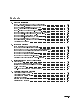
5. 4DISPLAY5 Softkey Reference 4DISPLAY5 Main . . . . . . 4DISPLAY5 Hard Copy . . . . 4DISPLAY5 Mass Storage . . 4DISPLAY5 Adjust Color . . 4DISPLAY5 Config Display . . . 4DISPLAY5 Address Map 4DISPLAY5 Misc . . . . . . NNNNNNNNNNNNNN . . . . . . . 5-3 5-6 5-12 5-15 5-21 5-26 5-29 Programming Commands (Quick Reference) . . . . . . . . . . . . . . . . . . Programming Commands (Extention Manual Pages) . . . . . . . . . . . . . .
Figures 1-1. 2-1. 2-2. 2-3. 2-4. 2-5. 2-6. 2-7. 2-8. 4-1. 4-2. 5-1. 5-2. 5-3. 5-4. 5-5. 5-6. 5-7. 5-8. 5-9. Available ac Power Cords . . . . . . . . . . . . . . . . . . . . . . . . . . 1-19 Line Voltage Selector . . . . . . . . . . . . . . . . . . . . . . . . . . . . 2-2 Line Fuse Removal and Replacement . . . . . . . . . . . . . . . . . . . . 2-3 display tests Menu Keys . . . . . . . . . . . . . . . . . . . . . . . . 2-8 Con dence Test . . . . . . . . . . . . . . . . . . . . . . . . . . . . . .
1 Hardware Installation This chapter contains information needed to prepare an HP 70004A color display for use in an HP 70000 Series modular measurement system. The information presented is general in nature; for more detailed information on cabling con gurations, module placement, and MSIB addressing, refer to the HP 70000 Modular Spectrum Analyzer Installation and Veri cation Manual. Step 1.
Step 1. Unpacking Your HP 70004A Color Display 1 Unpack your color display from its shipping container. 2 Inspect the shipping container and contents thoroughly to ensure that it was not damaged during shipment. If the container or cushioning material is damaged, check the contents of the shipment both mechanically and electrically. If the contents are damaged or defective, contact your nearest Hewlett-Packard Sales and Service O ce. (Refer to Table 2-2.
Step 2 (Optional). Installing an Instrument Keypad Step 2 (Optional). Installing an Instrument Keypad To remove an instrument keypad (with release button): 1. Depress the release button, located on the right-hand side of the keypad, and the instrument keypad should snap out. To install a custom instrument keypad (with release button): 1. Insert the left side of the keypad (2) into the front panel. 2. Press the right side of the keypad until it snaps into the front panel.
Step 2 (Optional). Installing an Instrument Keypad To remove an instrument keypad (without release button): 1. Insert a bladed screwdriver into the keypad's slot (1). 2. Gently pry the screw-driver's handle to the left. The keypad (2) will snap out of the front panel. To install a custom instrument keypad (without release button): 1. Insert the left side of the keypad (2) into the front panel. 2. Press the right side of the keypad until it snaps into the front panel.
Step 3 (Optional). Installing HP-HIL Devices Step 3 (Optional). Installing HP-HIL Devices To connect a HP-HIL keyboard and a mouse: 1. Inspect the two ends of each HP-HIL cable to locate an end with one black dot and an end with two black dots. 2. Plug the two-dot end of the HP-HIL cable into the display's two-dot connector.
Step 3 (Optional). Installing HP-HIL Devices To connect an HP mouse or track ball: Plug the two-dot end of the HP-HIL cable that came with the HP mouse or track ball into the keyboard's two-dot connector or the two-dot connector of the display; the HP mouse or track ball do not need a keyboard, they can be connected directly to the display. The HP-HIL interface supports most relative locator devices including the HP mouse and track ball.
Step 4. Connecting Rear Panel Cables Step 4. Connecting Rear Panel Cables To connect the display to another display or mainframe:1 2 ; 1. Connect an MSIB cable between the HP 70004A color display's MSIB OUT connector (1) and the HP 70001A mainframe's MSIB IN connector (2). 2. Connect an MSIB cable between the HP 70001A mainframe's MSIB OUT connector (3) and the HP 70004A color display's MSIB IN connector (4).
Step 5. Setting the MSIB and HP-IB Address To set the MSIB and HP-IB address switches: 1. Locate the address switches on the rear panel of the display. 2. Set the ve switches labeled COLUMN to the binary value of the display's MSIB column address. Setting the COLUMN address of the display, speci es both the MSIB address and the HP-IB address of the display.
Step 6 (Optional). Connecting for Remote HP-IB Operation Step 6 (Optional). Connecting for Remote HP-IB Operation To operate the display remotely: 1. Locate the address switches on the rear panel of the HP 70004A color display. 2. Set the HP-IB switch to the ON position. 3. Connect an HP-IB cable between the HP 70004A color display's HP-IB connector (1) and the HP 70001A mainframe's HP-IB connector (2). 4.
Step 7 (Optional). Connecting an HP-IB Disk Drive To connect an HP-IB disk drive 1. Locate the HP-IB address switches on the rear panel of the external HP-IB disk drive. 2. Set the HP-IB address switches to 0. Refer to the user's manual for your external HP-IB disk drive if you use a di erent HP-IB address. 3. Connect an HP-IB cable between the HP 70004A color display's HP-IB connector (1) and the external HP-IB disk drive's HP-IB connector (2).
Step 7 (Optional). Connecting an HP-IB Disk Drive Example of accessing an HP-IB disk drive through an HP 70900B local oscillator source. Example of using MSIB to connect to a remote antenna site.
Step 8 (Optional). Connecting a printer To connect a printer 1. Locate the printer address switches on the rear panel of the printer being connected. 2. Set the address switches to 1. Refer to the user's manual for your printer if you use a di erent printer address. 3. Connect an HP-IB cable between the HP 70004A color display's HP-IB connector (1) and the \HP-IB" connector (2) on the ITEL interface. (Refer to Table 1-2 for recommended ITEL interface models.) 4.
Step 8 (Optional).
Step 9 (Optional). Inserting a RAM Memory Card To insert a RAM memory card: 1. Locate the arrow printed on the card label. 2. Insert the card with the arrow on the card matching the arrow above the card-reader slot. 3. Press the card into the slot. When correctly inserted, approximately 19 mm (0.75 in) of the card is exposed. Memory cards provide storage media and access routines and instrument personalities; these are called down-loadable programs (DLPs).
Step 10. Connecting the AC Line Power Step 10. Connecting the AC Line Power 1 Con rm that the line-voltage selector is set to the proper ac line voltage. Failure to set the ac power input to the correct voltage could cause one of two things to happen when power is applied: If the switch is set to 115 V and the instrument is connected to 230 V, the fuse will blow. If the switch is set to 230 V and the instrument is connected to 115 V, the instrument will not turn on.
Step 10. Connecting the AC Line Power 2 Connect the ac power cord to the display or mainframe's rear panel.
Step 11 (Optional). Running the Con dence Tests Step 11 (Optional). Running the Con dence Tests 1 Press the 4DISPLAY5 key. 2 Press the Misc , display tests , and CONFID TEST menu keys to initiate the test. NNNNNNNNNNNNNN NNNNNNNNNNNNNNNNNNNNNNNNNNNNNNNNNNNNNNNNN NNNNNNNNNNNNNNNNNNNNNNNNNNNNNNNNNNN The Con dence Test checks the operation of roughly 90% of the HP 70004A color display.
Accessories and Options The accessories that are supplied with an HP 70004A color display, ordered separately, or as part of a precon gured HP 70000 Series modular measurement system are the same.
Accessories and Options Figure 1-1.
Accessories and Options ITEL Interface Models for Connecting Printers There are a number of Centronics converter models available for connecting printers to the HP-IB. These models are made by Intelligent Interfaces Inc. (800-842-0888) and are listed in the following table. Table 1-2.
2 If You Have Problems This section contains information to help identify and resolve some common problems that may occur with your color display before the need for extensive servicing. Symptoms of various problems are listed at the top of each page. Most symptoms have a brief description or explanation to help provide more insight into their cause. A possible cause for the symptom and a checklist of possible solutions are then presented. Use this checklist as an aid to correct the problem.
If the System's Power-On Self Test Fails Each time the HP 70000 Series modular spectrum analyzer system is turned on, the system runs through an initializing routine (power-on self test) during which the front panel STATUS LEDs on each module ash on momentarily and then turn o . The display also executes a power-on self-test when power is applied. If the test fails, the display terminates the sequence and displays an error on the screen in large block letters.
If the System's Power-On Self Test Fails mainframe. Also included in this housing is a spare fuse. The fuse is a 5 by 20 mm fuse rated at 6.3 A, 250 V (HP part number 2110-0703). This line fuse can be used with both 120 V and 230 V line voltage. Figure 2-2. Line Fuse Removal and Replacement Check the system interconnections. Check the address map as shown in Table 2-1. Run the Con dence Test. (Refer to \If You Need to Run Display Tests".) The Con dence Test checks the operation of about 90% of the display.
If You Have a Blank or Distorted Display To solve this problem: Verify that your display is powered on. Verify that the intensity is turned on. If necessary, obtain service from Hewlett-Packard. (Refer to \If You Need to Contact Hewlett-Packard".
If One of the HP 70004A Color Display Fault Indicators is On If One of the HP 70004A Color Display Fault Indicators is On Problems external to the display can cause the indicators to turn on. The HP 70004A color display has four fault indicators: An MSIB indicator on the upper-left corner of the front panel. A blinking red E in the status box in the upper-left corner of the display. A steady red E in the status box in the upper-left corner of the display.
If One of the HP 70004A Color Display Fault Indicators is On If you have a blinking E indicator The E indicator in the status box in the upper-left corner of the display is the same as the red LED marked \ERR" on other HP 70000 Series modules. Its purpose is to indicate an error detected in the system on MSIB row 0 of the address map.
If More Than One Module's Error Indicator is Flashing If More Than One Module's Error Indicator is Flashing The HP 70004A color display communicates with the HP 70000 Series modular spectrum analyzer system over the MSIB. When the STATUS ERR indicator LED on a particular module ashes at a 1 Hz rate, the module cannot communicate over the MSIB. To solve this problem: Try turning o the power to the system and then turning it on again.
If You Need to Run Display Tests The Display Tests are the display diagnostic and adjustment routines. The Display Tests screen is accessed by pressing 4DISPLAY5 Misc display tests . NNNNNNNNNNNNNN NNNNNNNNNNNNNNNNNNNNNNNNNNNNNNNNNNNNNNNNN WARNING Keep in mind that display internal adjustments or repairs should only be attempted by quali ed technical personnel. Figure 2-3.
If You Need to Run Display Tests Con dence Test ( CONFID TEST Menu Key) WWWWWWWWWWWWWWWWWWWWWWWWWWWWWWWWWWWWWWWWWWWWWW NNNNNNNNNNNNNNNNNNNNNNNNNNNNNNNNNNN Initiate the Display Con dence Test by pressing the CONFID TEST menu key. The Con dence Test checks the operation of roughly 90% of the display. If no fault is found, 6001 confidence test passed appears in the lower-left corner of the screen. If a fault is found, 6008 confidence test failed is displayed. To run the Display Con dence Test: 1.
If You Need to Run Display Tests Key Test Menu Key NNNNNNNNNNNNNNNNNNNNNNNNNN The KEY TEST menu key allows the user to check the mechanical and electrical operation of every front panel key on the display. To run the key test: 1. Press 4DISPLAY5 Misc display tests KEY TEST . NNNNNNNNNNNNNN NNNNNNNNNNNNNNNNNNNNNNNNNNNNNNNNNNNNNNNNN NNNNNNNNNNNNNNNNNNNNNNNNNN 2. Press any key on the display's front panel. The pressed key will be echoed on the screen if the key is working properly. 3.
If You Need to Run Display Tests Knob Test Menu Key NNNNNNNNNNNNNNNNNNNNNNNNNNNNN The KNOB TEST menu key allows the user to test the front panel knob on the display. To run the knob test: 1. Press 4DISPLAY5 Misc display tests KNOB TEST . NNNNNNNNNNNNNN NNNNNNNNNNNNNNNNNNNNNNNNNNNNNNNNNNNNNNNNN NNNNNNNNNNNNNNNNNNNNNNNNNNNNN 2. Turn the front panel knob clockwise slowly. The numbers in the center of the Knob Test display should increase one by one (from 00 to 39). 3.
If You Need to Run Display Tests Tumble Figures Menu Key While the tumble Note gures are running, the display cannot communicate on either HP-IB or MSIB. Nor can the display respond to any front panel keys except the back-arrow key 4 5 and the TUMBLE FIGURES menu keys used to select the various demonstration gures.
If You Need to Run Display Tests Display ID Menu Key When the 4DISPLAY5 Misc DISPLAY ID keys are pressed, the screen shows the following information: 16 squares with each of the current colors HP model number. Firmware version. MSIB address. HP-IB address (OFF if disabled with the rear panel switch). Custom Keypad ID Code. NNNNNNNNNNNNNN NNNNNNNNNNNNNNNNNNNNNNNNNNNNNNNN Figure 2-7.
If You Have to Clean the Display's Screen To clean the display's screen To avoid damaging the coating on the display screen, use a thin- lm cleaner such as Hewlett-Packard Video Clean Kit (HP part number 92193). The kit includes an abrasion-free cleaning cloth.
If You Need to Contact Hewlett-Packard If You Need to Contact Hewlett-Packard Before calling Hewlett-Packard or returning your color display, please read your warranty information. Warranty information is printed at the front of this document. In any correspondence or telephone conversations, refer to the color display by its full model number and full serial number. With this information, the Hewlett-Packard representative can determine whether your unit is still within its warranty period.
If You Need to Contact Hewlett-Packard A current list of Hewlett-Packard Service Centers can be accessed on the Internet at: http://www.tmo.hp.com/tmo/contacts/ If you do not have access to the Internet, one of the following Hewlett-Packard locations can direct you to your nearest Hewlett-Packard representative: Table 2-2.
Returning Your Color Display to Hewlett-Packard Returning Your Color Display to Hewlett-Packard Hewlett-Packard has sales and service o ces around the world to provide complete support for your color display. To obtain servicing information or to order replacement parts, contact the nearest Hewlett-Packard sales and service o ce listed in Table 2-2. Use the following procedure to return your color display to Hewlett-Packard: 1.
Returning Your Color Display to Hewlett-Packard Table 2-3.
3 Introducing the HP 70004A Color Display Summary In this chapter you will learn about: Main features of the HP 70004A color display. Regions of the display screen, and the kinds of information that can be found in each region. Front panel hard-labeled keys and their use. Instrument keypads that can be selected. Rear-panel connectors. Address switches. This chapter presents a rst look at the HP 70004A color display. You will be introduced to some of the main features.
Main Features The HP 70004A color display is a rugged structure into which modules of various widths can be placed; it serves as the \front panel" for instruments in the HP 70000 Series modular measurement system and provides a graphics display and front panel interface. It is possible to use one display with multiple measurement systems, one display for a single system, or even multiple displays for the same system.
Main Features Cooling Remote Programmability The ac power input is switchable between several ranges: 87|132 Vac, 47|66 Hz 174|264 Vac, 47|66 Hz 87|132 Vac, 356|444 Hz A fan provides cooling for both the display and up to four 1/8-width modules. The HP 70004A color display is programmed by modules in a low-level language resembling Hewlett-Packard Graphics Language (HP-GL). It also can be programmed directly through the Hewlett-Packard Interface Bus (HP-IB) in this same language.
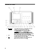
Front Panel Regions and Hard-Labeled Keys Regions of the Display Regions of the Display Screen The display screen is divided into six information regions. 1 2 3 4 5 6 status information The display uses the status information area to present system status information, such as the real-time clock readout and HP logo. graphics The graphics area, which can be subdivided into four windows, displays graphics and text.
Front Panel Regions and Hard-Labeled Keys System State (R L T S E A) R HP-IB1 Remote, on when the display is in the HP-IB remote mode. L HP-IB Listen, on when the display is addressed to listen on HP-IB. T HP-IB Talk, on when the display is addressed to talk on HP-IB. S HP-IB SRQ, on when the display is asserting SRQ (service request). E Error (red), on when there is an error in any module on ROW 0 of the address map.
Front Panel Regions and Hard-Labeled Keys Hard-Labeled Keys HP 70004A Color Display Front Panel Use the hard-labeled keys (permanently xed keys) above and below the display screen to perform such functions as: presetting the instrument, moving the keyboard between instruments in the system, changing parameters with step keys, and printing, as well as many other functions.
Front Panel Regions and Hard-Labeled Keys MSIB (2) The MSIB fault indicator light indicates the status of the MSIB. If the light is on, there is an MSIB problem or the bus is resetting. 4LCL5 (3) The local key reinstates front panel operation if the instrument has been under remote control. 4PLOT5 (4) Use the plot key to start a vector (HP-GL) plot output of the present display screen over HP-IB. Pressing the plot key initiates a vector plot dump over HP-IB to the plotter speci ed under Hard Copy .
Front Panel Regions and Hard-Labeled Keys inverse video on the softkey labels indicates which keys and conditions are selected. 4USER5 (7) The user key is used to access user-de ned menus or access down-loadable programs (DLPs). DLPs are one-button measurement routines capable of performing complex measurement sequences without a controller. Refer to you instruments operation manual for information about transferring functions from the 4MENU5 key to the 4USER5 key area.
Front Panel Regions and Hard-Labeled Keys The INSTR Key Display Screen NNNNNNNNNNNNNNNNN 4HOLD5 (10) The hold key is used to deactivate an active function and prevent further control setting changes. NNNNNNNNNNNNNN For example, on a spectrum analyzer, if SPAN menu key has just been set to 1 MHz, it remains the active function. So if the knob is turned or the step keys are pressed accidentally, the span will change to a new value.
Front Panel Regions and Hard-Labeled Keys Knob (13) Use the knob to change parameters and select other operating values; this knob is also referred to as an RPG [Rotary Pulse Generator] knob. 5 4 4 5 4 5 (14) The step keys change parameters up or down. Numeric Keypad (405|495) (15) The numeric keypad are used to enter numbers. The number is entered upon pressing the ENTER menu key. NNNNNNNNNNNNNNNNN 4LINE5 (16) The line key switches the display's line power on and o .
Instrument Keypads for a Spectrum Analyzer Instrument Keypads for a Spectrum Analyzer A spectrum analyzer instrument keypad is shipped with each HP 70900B local oscillator source. This keypad, designed to plug into the front of an HP 70004A color display, allows the operator to access or activate spectrum analyzer control functions from the front of the HP 70004A color display. The spectrum analyzer instrument keypad can be used with the current LO module and HP 70004A color display rmware.
Instrument Keypads for a Spectrum Analyzer Instrument Keypad Function Keys Description of Function Function Key 4CENTER5 Activates the center frequency function, which can then be tuned continuously over the range of the spectrum analyzer using the data controls. SPAN5 Changes the total display frequency range symmetrically about the center frequency. REF LEVEL5 Changes the absolute amplitude power or voltage represented by the top graticule on the screen.
HP-HIL Keyboards HP-HIL Keyboards The Hewlett-Packard Human Interface Link (HP-HIL) provides an interface to the system by means of an HP 46021A or HP 98203C keyboard. The keys of an HP-HIL keyboard correspond to the functional softkeys of a Modular Measurement \C" System spectrum analyzer. The keyboard cable is plugged into the HP-HIL connector located on the front of the HP 70004A color display. (Refer to \Step 3 (Optional). Installing HP-HIL Devices" in Chapter 1.
HP-HIL Keyboards Functional Keycodes HP 46021A Keyboard This keyboard has eight function keys along the top row. The function keys 4f15 through 4f75 on the keyboard correspond to the right-hand softkeys on the display from top to bottom, respectively. When the 4SHIFT5 key is pressed at the same time a function key is pressed, 4f15 through 4f75 on the keyboard correspond to the left-hand softkeys on the display from top to bottom, respectively.
HP-HIL Keyboards Alpha keys NNNNNNNNNNNNNNNNN NNNNNNNNNNNNNNNNNNNNNNN On either keyboard, after the TITLE or COMMAND mode softkeys have been selected, 4A5-4Z5, 4a5-4z5, punctuation, 4Ins5 and 4DEL5 are used to insert or delete characters into a title or command. When these keys are pressed, the response is the same as with the TITLE or COMMAND mode menu blocks. A title or command can be typed using the HP-HIL keyboard.
Rear-Panel Connectors and Address Switches HP 70004A Color Display Rear-Panel Connectors 1 HP-IB 2 MSIB 3 RGB The Hewlett-Packard Interface Bus (HP-IB) provides IEEE-488 communication between the display, controllers, other HP-IB instruments, and each module installed in the display that implements HP-IB. The Modular System Interface Bus (MSIB) is the high-speed digital bus used by master and slave modules and other elements for exchanging control information and data.
Rear-Panel Connectors and Address Switches A display section is an independent element. When you set the HP-IB switch to 0 (OFF), the HP-IB interface for the display section only is turned o . Modules plugged into the display are una ected and may still talk to each other through HP-IB or communicate over the rear panel HP-IB connector. The HP-IB switch does not disrupt instrument operation.
Rear-Panel Connectors and Address Switches TEST MODE When you set the Test Mode switch to 1 (ON), the display goes into a special test mode at power-up. For normal operation, set this to 0 (OFF).
4 Operating/Local MSIB Operation Summary In this chapter you will learn about: Con guring your system and assigning instruments (modules) to di erent windows. Changing the color settings and system clock time used by the display. Printing and plotting display screens. Saving and retrieving information. This chapter prepares you for your rst steps in using the HP 70004A color display in a system.
Con guring Display Windows In this section, you will learn how to build or stack windows on your display and assign the keyboard or display or both to an instrument by using various softkey menus. After you have con gured your system, you can view your con guration and then start using it, or purge it and start over.
Con guring Display Windows To build 1, 2, or 4 windows on the display 1. Press 4DISPLAY5 Config Display build window NNNNNNNNNNNNNNNNNNNNNNNNNNNNNNNNNNNNNNNNNNNN NNNNNNNNNNNNNNNNNNNNNNNNNNNNNNNNNNNNNN 2. Press BUILD 1 WINDOW or BUILD 2 WINDOWS or BUILD 4 WINDOWS NNNNNNNNNNNNNNNNNNNNNNNNNNNNNNNNNNNNNNNNNNNN NNNNNNNNNNNNNNNNNNNNNNNNNNNNNNNNNNNNNNNNNNNNNNN NNNNNNNNNNNNNNNNNNNNNNNNNNNNNNNNNNNNNNNNNNNNNNN 3. Press assign window . NNNNNNNNNNNNNNNNNNNNNNNNNNNNNNNNNNNNNNNNN 4.
Con guring Display Windows To stack 2 or 4 windows on the display 1. Press 4DISPLAY5 Config Display build window . NNNNNNNNNNNNNNNNNNNNNNNNNNNNNNNNNNNNNNNNNNNN NNNNNNNNNNNNNNNNNNNNNNNNNNNNNNNNNNNNNN 2. Press STACK 2 WINDOWS or STACK 4 WINDOWS NNNNNNNNNNNNNNNNNNNNNNNNNNNNNNNNNNNNNNNNNNNNNNN NNNNNNNNNNNNNNNNNNNNNNNNNNNNNNNNNNNNNNNNNNNNNNN 3. Press assign window . NNNNNNNNNNNNNNNNNNNNNNNNNNNNNNNNNNNNNNNNN 4. Press MSIB COLUMN to assign an instrument to the currently selected window.
Con guring Display Windows To build custom sized windows on the display 1. Press 4DISPLAY5 DISPLAY PRESET Config Display . NNNNNNNNNNNNNNNNNNNNNNNNNNNNNNNNNNNNNNNNNNNN NNNNNNNNNNNNNNNNNNNNNNNNNNNNNNNNNNNNNNNNNNNN 2. Press build window custom windows SELECT WINDOW . NNNNNNNNNNNNNNNNNNNNNNNNNNNNNNNNNNNNNN NNNNNNNNNNNNNNNNNNNNNNNNNNNNNNNNNNNNNNNNNNNN NNNNNNNNNNNNNNNNNNNNNNNNNNNNNNNNNNNNNNNNN 3.
Con guring Display Windows To establish a link to an instrument 1. Press 4DISPLAY5 NEXT INSTR . NNNNNNNNNNNNNNNNNNNNNNNNNNNNNNNN If the display does not have a link to an instrument, it will look for the instrument with the lowest column address on the MSIB and allocate the entire screen and the 14 softkeys to that instrument. If a link already exists, the display will select the instrument with the next higher address (following the sequence. . . . 28, 29, 30, 0, 1, 2. . . . ). 2.
Con guring Display Windows To view column and row addresses in the address map 1. Press 4DISPLAY5 Address Map ADJUST COLUMN . NNNNNNNNNNNNNNNNNNNNNNNNNNNNNNNNNNN NNNNNNNNNNNNNNNNNNNNNNNNNNNNNNNNNNNNNNNNN 2. Turn the knob until the rectangle encompasses an instrument on ROW 0 or until it is beneath an instrument in the same column. To select modules from the vertical columns, use ADJUST ROW along with 445 and 455 to place the rectangle around the module of interest.
Con guring Display Windows To assign the display (only) to an instrument 1. Press 4DISPLAY5 Address Map ADJUST COLUMN . NNNNNNNNNNNNNNNNNNNNNNNNNNNNNNNNNNN NNNNNNNNNNNNNNNNNNNNNNNNNNNNNNNNNNNNNNNNN 2. Turn the knob until the rectangle encompasses an instrument on ROW 0. 3. Press the ASSIGN DISPLAY softkey. NNNNNNNNNNNNNNNNNNNNNNNNNNNNNNNNNNNNNNNNNNNN The screen will be immediately allocated to that module. If the module is ready to put out trace information, the information will be displayed. 4.
Con guring Display Windows To assign both the display and keyboard to an instrument 1. Press 4DISPLAY5 Address Map ADJUST COLUMN . NNNNNNNNNNNNNNNNNNNNNNNNNNNNNNNNNNN NNNNNNNNNNNNNNNNNNNNNNNNNNNNNNNNNNNNNNNNN 2. Turn the knob until the rectangle encompasses an instrument on ROW 0. 3. Press ASSIGN BOTH 4MENU5.
Con guring Display Windows To set the HP-IB/MSIB address of the HP 70004A color display 1. Press 4DISPLAY5 Address Map ADJUST COLUMN . NNNNNNNNNNNNNNNNNNNNNNNNNNNNNNNNNNN NNNNNNNNNNNNNNNNNNNNNNNNNNNNNNNNNNNNNNNNN 2. Turn the knob so the rectangle stops on the module that you want to set the HP-IB address on; in this example, select the HP 70004A color display. 3. Press the HP-IB ADDRSET NNNNNNNNNNNNNNNNNNNNNNNNNNNNNNNNNNNNNNNNN 4. Enter the new address using the keypad.
Con guring Display Windows To show system con gurations 1. Press 4DISPLAY5 Config Display SHOW CONFIG . NNNNNNNNNNNNNNNNNNNNNNNNNNNNNNNNNNNNNNNNNNNN NNNNNNNNNNNNNNNNNNNNNNNNNNNNNNNNNNN 2. In addition to the current con guration that is shown, use the 445 and 455 keys to view Con guration Registers 1 through 4. These other con guration registers can be loaded with information using SAVE CONFIG . (Refer to the section \To save a system con guration".
Con guring Display Windows To save a system con guration 1. Press 4DISPLAY5 Config Display . NNNNNNNNNNNNNNNNNNNNNNNNNNNNNNNNNNNNNNNNNNNN 2. Select a number between 1 and 4 from the keypad or HP-HIL keyboard and press ENTER . (If you make an error, press 4 5 to return to the previous menu. Repeat your selection with the corrected entry if necessary.) 3. Press SAVE CONFIG .
Con guring Display Windows To recall a system con guration 1. Press 4DISPLAY5 Config Display . NNNNNNNNNNNNNNNNNNNNNNNNNNNNNNNNNNNNNNNNNNNN 2. Select a number between 1 and 4 from the keypad or HP-HIL keyboard and press ENTER . (If you make an error, press 4 5 to return to the previous menu. Repeat your selection with the corrected entry if necessary.) 3. Press RECALL CONFIG .
Con guring Display Windows To purge a window con guration 1. Press 4DISPLAY5 Config Display purge window . NNNNNNNNNNNNNNNNNNNNNNNNNNNNNNNNNNNNNNNNNNNN NNNNNNNNNNNNNNNNNNNNNNNNNNNNNNNNNNNNNN 2. Press EXECUTE or select a number between 1 and 4 from the keypad or HP-HIL keyboard and press ENTER to specify a particular window to be purged. (If you make an error, press 4 5 to return to the previous menu.) A green border outlines the selected window that is to be purged.
Con guring Display Windows To clear the display 1. Press 4DISPLAY5 DISPLAY PRESET . NNNNNNNNNNNNNNNNNNNNNNNNNNNNNNNNNNNNNNNNNNNN This key sequence clears the display screen, all errors, the HP-IB output bu er, and assigns the entire display screen to the last instrument controlled by the keyboard. A display preset is di erent from an instrument preset. An instrument preset would place all of an instruments settings to their default (preset) value and would not a ect the con guration of the display.
Con guring Display Colors Display colors have been preset with a set of default colors which you may choose to change in order to suit environmental needs, individual preferences, or to accommodate color-de cient vision. The display's default colors have been chosen to maximize your ability to comfortably discern the di erence between on-screen colors. We recommend these colors for normal use. They provide a suitable contrast that is easy to view for long periods of time.
Con guring Display Colors To customize display colors The following steps will change the background element color. 1. Press 4DISPLAY5 Adjust Color edit colors . NNNNNNNNNNNNNNNNNNNNNNNNNNNNNNNNNNNNNN NNNNNNNNNNNNNNNNNNNNNNNNNNNNNNNNNNN 2. Press BACKGROUND and rotate the knob clockwise and counter-clockwise; you should notice that the hue changes. 3. Press RGB . NNNNNNNNNNNNNNNNNNNNNNNNNNNNNNNN NNNNNNNNNNN 4. Press GREEN and use the 445 and 455 keys to change the color. NNNNNNNNNNNNNNNNN 5.
Con guring Display Colors To change the monochrome display to di erent shades of green 1. Press 4DISPLAY5 Adjust Color MONOCHROME . NNNNNNNNNNNNNNNNNNNNNNNNNNNNNNNNNNNNNN NNNNNNNNNNNNNNNNNNNNNNNNNNNNNNNN 2. Press edit colors Color X (where X is 1, 2, 3, . . . 10). NNNNNNNNNNNNNNNNNNNNNNNNNNNNNNNNNNN NNNNNNNNNNNNNNNNNNNNNNN 3. Press HSL/RGB GREEN . NNNNNNNNNNNNNNNNNNNNNNN NNNNNNNNNNNNNNNNN 4.
Con guring Display Colors To recall custom display colors 1. Press 4DISPLAY5 Adjust Color RECALL COLORS . NNNNNNNNNNNNNNNNNNNNNNNNNNNNNNNNNNNNNN NNNNNNNNNNNNNNNNNNNNNNNNNNNNNNNNNNNNNNNNN 2. Select a number between 1 and 4 from the keypad or HP-HIL keyboard and press ENTER . NNNNNNNNNNNNNNNNN The number that is selected designates one of four color-save registers where the on-screen display colors were saved with SAVE COLORS .
Con guring the Display Clock The HP 70004A color display will work normally without the clock being set to any particular time, but it is a good idea to set the clock to correspond to your local time so that any information that you store or print is given a correct time stamp (time stamp shows: hours, minutes, seconds, month, day, and year).
Con guring the Display Clock To set the display clock 1. Press 4DISPLAY5 Misc clock . NNNNNNNNNNNNNN NNNNNNNNNNNNNNNNN 2. Press CLOCK DISPLAY Set Clock . NNNNNNNNNNNNNNNNNNNNNNNNNNNNNNNNNNNNNNNNN NNNNNNNNNNNNNNNNNNNNNNNNNNNNN 3. Enter your current date: Example: Change the date to DEC 25, 1997. a. Press MONTH 415 425 ENTER . NNNNNNNNNNNNNNNNN NNNNNNNNNNNNNNNNN b. Press DAY 425 455 ENTER . NNNNNNNNNNN NNNNNNNNNNNNNNNNN c. Press YEAR 415 495 495 475 ENTER . NNNNNNNNNNNNNNNNN NNNNNNNNNNNNNN 4.
Printing and Plotting To print to an HP LaserJet Series printer : : : : : : : : : : : : : : : : : : : : : : : : : : : : : : : : : : : : : : : : : : : : : : : : : : : 4-23 To print to an HP-IB printer : : : : : : : : : : : : : : : : : : : : : : : : : : : : : : : : : : : : : : : : : : : : : : : : : : : : : : : : : : : : : : : : : 4-24 To print to an HP PaintJet printer : : : : : : : : : : : : : : : : : : : : : : : : : : : : : : : : : : : : : : : : : : : : : : : : : : : : : : : : : : 4-25 To print to an HP Thi
Printing and Plotting To print to an HP LaserJet Series printer Because color printers introduced a new standard not supported by the Note HP 70004A color display, the following information applies only to black and white printers. 1. If system controller is connected, release the system controller from the HP-IB.
Printing and Plotting To print to an HP-IB printer To follow this example, you may need to enter the address of your printer into Note the Hard Copy Menu and specify whether the menu keys are to be printed. (Refer to printer address and KEY COPY under \4DISPLAY5 Hard Copy " in Chapter 5.) NNNNNNNNNNNNNNNNNNNNNNNNNNNNNNNNNNNNNNNNNNNNNNN NNNNNNNNNNNNNNNNNNNNNNNNNNNNN NNNNNNNNNNNNNNNNNNNNNNNNNN 1. If system controller is connected, release the system controller from the HP-IB.
Printing and Plotting To print to an HP PaintJet printer The term high resolution that is used throughout this procedure refers to Note 180 dpi resolution printer dumps. 1. Press 4DISPLAY5 Hard Copy printer config . NNNNNNNNNNNNNNNNNNNNNNNNNNNNN NNNNNNNNNNNNNNNNNNNNNNNNNNNNNNNNNNNNNNNNNNNN 2. Press PAINTJT COLOR . NNNNNNNNNNNNNNNNNNNNNNNNNNNNNNNNNNNNNNNNN NNNNNNNNNNNNNNNNNNNNNNNNNNNNNNNNNNNNNNNNN NNNNNNNNNNNNNNNNNNNNNNNNNNNNNNNNNNNNNNNNN PAINTJT COLOR is the default printer mode.
Printing and Plotting To print to an HP ThinkJet printer The term high resolution that is used throughout this procedure refers to Note 180 dpi resolution. 1. Press 4DISPLAY5 Hard Copy printer config . NNNNNNNNNNNNNNNNNNNNNNNNNNNNN NNNNNNNNNNNNNNNNNNNNNNNNNNNNNNNNNNNNNNNNNNNN 2. Press THINK JET . NNNNNNNNNNNNNNNNNNNNNNNNNNNNN 3.
Printing and Plotting To set the printer address of a non-MMS printer 1. Press 4DISPLAY5 Hard Copy printer address . NNNNNNNNNNNNNNNNNNNNNNNNNNNNN NNNNNNNNNNNNNNNNNNNNNNNNNNNNNNNNNNNNNNNNNNNNNNN 2. Press HP-IB TLK/LSN and specify the HP-IB address of the printer. (Default is 1.) NNNNNNNNNNNNNNNNNNNNNNNNNNNNNNNNNNNNNNNNN You can select an HP-IB address through the numeric keypad or HP-HIL keyboard and press ENTER . (If you make an error, press 4 5 to return to the previous menu.
Printing and Plotting To set the plotter con guration 1. Press 4DISPLAY5 Hard Copy plotter config . NNNNNNNNNNNNNNNNNNNNNNNNNNNNN NNNNNNNNNNNNNNNNNNNNNNNNNNNNNNNNNNNNNNNNNNNN 2. Press SINGLE PEN or SIX PENS . NNNNNNNNNNNNNNNNNNNNNNNNNNNNNNNN NNNNNNNNNNNNNNNNNNNNNNNNNN NNNNNNNNNNNNNNNNNNNNNNNNNNNNNNNN SINGLE PEN is used to select a single pen for the whole drawing. NNNNNNNNNNNNNNNNNNNNNNNNNN SIX PENS is used to select that six di erent color pens be used for the drawing. 3.
Printing and Plotting To set the plotter address of an MMS plotter 1. Press 4DISPLAY5 Hard Copy plotter address . NNNNNNNNNNNNNNNNNNNNNNNNNNNNN NNNNNNNNNNNNNNNNNNNNNNNNNNNNNNNNNNNNNNNNNNNNNNN 2. Press MSIB COLUMN and specify the MSIB address of the plotter. (Default is ROW 0 and COLUMN 1.) You can select an MSIB address through the numeric keypad or HP-HIL keyboard and press ENTER . (If you make an error, press 4 5 to return to the previous menu.
Selecting and Saving to External Mass Storage Devices The previously described procedure, \To save a system con guration", does not save information permanently.
Selecting and Saving to External Mass Storage Devices To save your work to a permanent storage media device 1. Set the msi [mass storage is] of the HP 70004A color display to either an HP-IB disk drive or a memory card with one of the following procedures in this section. To select an HP-IB disk drive as a storage device To select the memory card as a mass storage device 2.
Selecting and Saving to External Mass Storage Devices To select an HP-IB disk drive as a storage device 1. Press 4DISPLAY5 Mass Storage msi HP-IB disk . NNNNNNNNNNNNNNNNNNNNNNNNNNNNNNNNNNNNNN NNNNNNNNNNN NNNNNNNNNNNNNNNNNNNNNNNNNNNNNNNN 2. Press HP-IB ADDRESS . NNNNNNNNNNNNNNNNNNNNNNNNNNNNNNNNNNNNNNNNN Enter the HP-IB ADDRESS of the HP-IB disk. (Default is 0.) 3. Press UNIT NUMBER . NNNNNNNNNNNNNNNNNNNNNNNNNNNNNNNNNNN Enter the UNIT NUMBER of the HP-IB disk.
Selecting and Saving to External Mass Storage Devices To select the memory card as a mass storage device 1. Press 4DISPLAY5 Mass Storage msi MEMORY CARD NNNNNNNNNNNNNNNNNNNNNNNNNNNNNNNNNNNNNN NNNNNNNNNNN NNNNNNNNNNNNNNNNNNNNNNNNNNNNNNNNNNN Data can be stored directly on the memory card by instrument modules without the use of an external disk drive.
Selecting and Saving to External Mass Storage Devices To install a memory card CAUTION Improper card insertion can cause error messages to occur, but generally does not damage the card or instrument. Care must be taken, however, not to force the card into the card reader slot. 1. Locate the arrow printed on the card label. 2. Insert the card with the arrow on the card matching the arrow above the card-reader slot. 3. Press the card into the slot. When correctly inserted, approximately 19 mm (0.
Selecting and Saving to External Mass Storage Devices To change the battery on a RAM memory card CAUTION RAM memory cards must be installed in an HP 70004A color display when the battery is removed (ROM memory cards do not have a battery). Be sure that the HP 70004A color display is powered on before removing the battery. If the battery is removed while the memory card is not installed in the HP 70004A color display, all data in the RAM memory card is lost.
Selecting and Saving to External Mass Storage Devices The battery is located beside the RAM memory card's write-protect switch on the opposite end of the connector. The RAM memory card requires power. Items stored in the RAM memory card remain as long as the card has su cient power (ROM memory cards do not require continuous power). The HP 70004A color display provides power to the memory card when it is installed and continues to supply power only when the HP 70004A color display is powered on.
Selecting and Saving to External Mass Storage Devices To format a memory card CAUTION FORMAT erases the contents of the currently selected memory. Be sure to NNNNNNNNNNNNNNNNNNNN NNNNNNNNNNNNNNNNNNNN select the desired memory before executing FORMAT . Internal memory is selected automatically when power is applied. 1. Insert the memory card. 2. Press 4DISPLAY5 Misc MORE MSIB CARD .
Miscellaneous User Tasks To erase volatile and non-volatile user RAM : : : : : : : : : : : : : : : : : : : : : : : : : : : : : : : : : : : : : : : : : : : : : : : : 4-38 To turn the HP logo ON or OFF : : : : : : : : : : : : : : : : : : : : : : : : : : : : : : : : : : : : : : : : : : : : : : : : : : : : : : : : : : : : : 4-38 To examine errors reported by the display : : : : : : : : : : : : : : : : : : : : : : : : : : : : : : : : : : : : : : : : : : : : : : : : : : 4-38 To view current display information (
Miscellaneous User Tasks To view current display information ( rmware, address, model, etc.) 1. Press 4DISPLAY5 Misc DISPLAY ID . NNNNNNNNNNNNNN NNNNNNNNNNNNNNNNNNNNNNNNNNNNNNNN NNNNNNNNNNNNNNNNNNNNNNNNNNNNNNNN DISPLAY ID displays the following information: Color Palette (In 16 boxes centered on the top two rows. Colors 0|7 are on the top row, and 8|15 on the next row down.
5 4DISPLAY5 Softkey Reference Summary In this chapter you will learn about: Softkeys available when 4DISPLAY5 is selected and what each softkey can do. This chapter introduces the conventions used in the softkey menus. Then all of the softkeys available through the 4DISPLAY5 key are described. The softkeys are described according to their position on the display menus.
When you rst start your HP 70004A color display, an initial set of top-level softkeys will appear. Depending on whether 4DISPLAY5, 4USER5, or 4MENU5 is selected, a di erent set of top-level softkeys are available; the softkey set is dependent on the instrument in control of the keyboard. Selecting one of the top-level softkeys on the left side of the display allows access to a menu of softkeys on the right side of the display.
DISPLAY5 Main 4 4DISPLAY5 NNNNNNNNNNNNNN Main aaaaaaaaaaaaaaaaaaaaaa Figure 5-1. Main Keys NNNNNNNNNNNNNNNNNNNNNNNNNNNNNNNNNNNNNNNNNNNN NNNNNNNNNNNNNN NNNNNNNNNNNNNNNNNNNNNNNNNNNNNNNN NNNNNNNNNNNNNNNNNNNNNNNNNNNNNNNNNNNNNNNNN The Main softkey accesses the DISPLAY PRESET , NEXT INSTR , REPORT ERRORS , and INTEN ADJUST functions. The main menu is selected whenever the 4DISPLAY5 key is pressed.
DISPLAY5 Main NNNNNNNNNNNNNN 4 NEXT INSTR WWWWWWWWWWWWWWWWWWWWWWWWWWWWWWWWWWWWWWWWWW Key Path: Actions: DISPLAY5 NEXT INSTR 4 NNNNNNNNNNNNNNNNNNNNNNNNNNNNNNNN Establishes initial contact between the display and a single instrument. Steps to the next instrument on row 0 of the address map. Pressing 445 or 455 causes a search up or down through the address map for the next instrument. Establishes a link between the display and one instrument at a time.
DISPLAY5 Main 4 NNNNNNNNNNNNNN REPORT ERRORS WWWWWWWWWWWWWWWWWWWWWWWWWWWWWWWWWWWWWWWWWWWWWWWWWWWWWW Key Path: DISPLAY5 REPORT ERRORS NNNNNNNNNNNNNNNNNNNNNNNNNNNNNNNNNNNNNNNNN 4 Actions: When an instrument or module has an error, it informs every instrument that resides on row 0 of the address map. This will cause an E (the E is red on the HP 70004A color display) to appear in the status box of every display.
4DISPLAY5 Hard Copy aaaaaaaaaaaaaaaaaaaaaaaaaaaaaaaaaaaaaaaaaaaaa Figure 5-2.
DISPLAY5 Hard Copy 4 NNNNNNNNNNNNNNNNNNNNNNNNNNNNN NNNNNNNNNNNNNNNNNNNNNNNNNNNNN The Hard Copy softkey accesses printing and plotting functions. Also covered are the de nitions (addresses, plot sizes, and so on) that are used for printing and plotting.
DISPLAY5 Hard Copy NNNNNNNNNNNNNNNNNNNNNNNNNNNNN 4 printer address WWWWWWWWWWWWWWWWWWWWWWWWWWWWWWWWWWWWWWWWWWWWWWWWWWWWWWWWWWWWW Key Path: DISPLAY5 Hard Copy printer address NNNNNNNNNNNNNNNNNNNNNNNNNNNNN NNNNNNNNNNNNNNNNNNNNNNNNNNNNNNNNNNNNNNNNNNNNNNN 4 Actions: NNNNNNNNNNNNNNNNNNNNNNNNNNNNNNNNNNNNNNNNNNNNNNN printer address de nes the HP-IB address of the output printer.
DISPLAY5 Hard Copy 4 NNNNNNNNNNNNNNNNNNNNNNNNNNNNN Table 5-2.
DISPLAY5 Hard Copy NNNNNNNNNNNNNNNNNNNNNNNNNNNNN 4 plotter address WWWWWWWWWWWWWWWWWWWWWWWWWWWWWWWWWWWWWWWWWWWWWWWWWWWWWWWWWWWWW Key Path: DISPLAY5 Hard Copy plotter address NNNNNNNNNNNNNNNNNNNNNNNNNNNNN NNNNNNNNNNNNNNNNNNNNNNNNNNNNNNNNNNNNNNNNNNNNNNN 4 Actions: NNNNNNNNNNNNNNNNNNNNNNNNNNNNNNNNNNNNNNNNNNNNNNN plotter address de nes the HP-IB address of the hardcopy output plotter.
DISPLAY5 Hard Copy 4 NNNNNNNNNNNNNNNNNNNNNNNNNNNNN the HP 70900B local oscillator source sends a CY command to the display over MSIB. The DEFAULT VALUES softkey sets each of the other functions in this menu to the following default settings: NNNNNNNNNNNNNNNNNNNNNNNNNNNNNNNNNNNNNNNNNNNN Table 5-3. Default Values of copy options NNNNNNNNNNNNNNNNNNNNNNNNNNNNNNNNNNNNNN PRINTER IS: PLOTTER IS: KEYCOPY: HP LOGO COPY: CLOCK COPY: PAGE EJECT: COPY IS: PLOTTER PARAMS: Note HP-IB Talk/Listen at address 1.
4DISPLAY5 Mass Storage aaaaaaaaaaaaaaaaaaaaaaaaaaaaaaaaaaaaaaaaaaaaaaaaaaaaaaaaaaa Figure 5-3. Mass Storage Keys NNNNNNNNNNNNNNNNNNNNNNNNNNNNNNNNNNNNNN The Mass Storage softkey accesses two separate memory devices for saving and recalling instrument states, data, traces, user keys, limit lines, and programs (DLPs).
DISPLAY5 Mass Storage 4 NNNNNNNNNNNNNNNNNNNNNNNNNNNNNNNNNNNNNN Figure 5-4. Example of an HP 70900B Local Oscillator Source Accessing an HP-IB Disk Drive Figure 5-5.
DISPLAY5 Mass Storage NNNNNNNNNNNNNNNNNNNNNNNNNNNNNNNNNNNNNN 4 HP-IB disk WWWWWWWWWWWWWWWWWWWWWWWWWWWWWWWWWWWWWWWWWW Key Path: DISPLAY5 Mass Storage msi HP-IB disk NNNNNNNNNNNNNNNNNNNNNNNNNNNNNNNNNNNNNN NNNNNNNNNNN NNNNNNNNNNNNNNNNNNNNNNNNNNNNNNNN 4 Actions: NNNNNNNNNNNNNNNNNNNNNNNNNNNNNNNN HP-IB disk sets the mass storage device to the external HP-IB disk drive. Data can be stored on the disk by instrument modules using the display.
DISPLAY5 Adjust Color 4 4DISPLAY5 NNNNNNNNNNNNNNNNNNNNNNNNNNNNNNNNNNNNNN Adjust Color aaaaaaaaaaaaaaaaaaaaaaaaaaaaaaaaaaaaaaaaaaaaaaaaaaaaaaaaaaa Figure 5-6.
DISPLAY5 Adjust Color NNNNNNNNNNNNNNNNNNNNNNNNNNNNNNNNNNNNNN 4 Display colors have been preset with a set of default colors which you may choose to change in order to suit environmental needs, individual preferences, or to accommodate color-de cient vision. The display's default colors have been chosen to maximize your ability to comfortably discern the di erence between on-screen colors. We recommend these colors for normal use.
DISPLAY5 Adjust Color NNNNNNNNNNNNNNNNNNNNNNNNNNNNNNNNNNNNNN 4 that represent hue (the pure color), saturation (the ratio of the pure color mixed with white), and luminosity (the brightness-per-unit area). (Red, Green, Blue) The RGB menu allows the user to turn the knob to change the output of the three primary light sources (one each of red, green, and blue) that make up any color. The parameters specify the intensity of each of the light sources. RGB Table 5-4.
DISPLAY5 Adjust Color NNNNNNNNNNNNNNNNNNNNNNNNNNNNNNNNNNNNNN 4 MONOCHROME WWWWWWWWWWWWWWWWWWWWWWWWWWWWWWWWWWWWWWWWWW Key Path: DISPLAY5 Adjust Color MONOCHROME NNNNNNNNNNNNNNNNNNNNNNNNNNNNNNNNNNNNNN NNNNNNNNNNNNNNNNNNNNNNNNNNNNNNNN 4 Actions: NNNNNNNNNNNNNNNNNNNNNNNNNNNNNNNN MONOCHROME sets the display screen to green monochrome. Table 5-5.
DISPLAY5 Adjust Color Table 5-6.
DISPLAY5 Adjust Color Table 5-8.
DISPLAY5 Config Display 4 4DISPLAY5 NNNNNNNNNNNNNNNNNNNNNNNNNNNNNNNNNNNNNNNNNNNN Config Display aaaaaaaaaaaaaaaaaaaaaaaaaaaaaaaaaaaaaaaaaaaaaaaaaaaaaaaaaaaaaaaaaaaaa Figure 5-7.
DISPLAY5 Config Display NNNNNNNNNNNNNNNNNNNNNNNNNNNNNNNNNNNNNNNNNNNN 4 NNNNNNNNNNNNNNNNNNNNNNNNNNNNNNNNNNNNNNNNNNNN Config Display allows exible display formatting of the HP 70000 Series modular measurement system. Up to four windows can be con gured to display the traces, annotation, graticule, and measurement results of four di erent instruments on a single display.
DISPLAY5 Config Display NNNNNNNNNNNNNNNNNNNNNNNNNNNNNNNNNNNNNNNNNNNN 4 window, numbered 1 through 4, by using any data entry method (step-keys, display knob, numeric keypad, or softkey). If the keypad is used to enter the window number, the user must press ENTRY to nish the entry. NNNNNNNNNNNNNNNNN Softkeys Available Under custom windows NNNNNNNNNNNNNNNNNNNNNNNNNNNNNNNNNNNNNNNNNNNN The values of X-min, Y-min, X-max, Y-max represent the distances of the lines from the origin.
DISPLAY5 Config Display NNNNNNNNNNNNNNNNNNNNNNNNNNNNNNNNNNNNNNNNNNNN 4 BUILD (#) WINDOW(S) WWWWWWWWWWWWWWWWWWWWWWWWWWWWWWWWWWWWWWWWWWWWWWWWWWWWWWWWWWWWWWWWWWWWWWWWWWWWW Build 1, 2, or 4 Windows Key Path: DISPLAY5 Config Display build window BUILD (#) WINDOW(S) 4 Actions: NNNNNNNNNNNNNNNNNNNNNNNNNNNNNNNNNNNNNNNNNNNN NNNNNNNNNNNNNNNNNNNNNNNNNNNNNNNNNNNNNN NNNNNNNNNNNNNNNNNNNNNNNNNNNNNNNNNNNNNNNNNNNNNNNNNNNNNNNNNNN NNNNNNNNNNNNNNNNNNNNNNNNNNNNNNNNNNNNNNNNNNNNNNNNNNNNNNNNNNN BUILD (#) WINDOW(S) displ
DISPLAY5 Config Display 4 NNNNNNNNNNNNNNNNNNNNNNNNNNNNNNNNNNNNNNNNNNNN assign window WWWWWWWWWWWWWWWWWWWWWWWWWWWWWWWWWWWWWWWWWWWWWWWWWWWWWW Key Path: DISPLAY5 Config Display assign window NNNNNNNNNNNNNNNNNNNNNNNNNNNNNNNNNNNNNNNNNNNN NNNNNNNNNNNNNNNNNNNNNNNNNNNNNNNNNNNNNNNNN 4 Actions: NNNNNNNNNNNNNNNNNNNNNNNNNNNNNNNNNNNNNNNNN assign window selects the instrument that will be assigned to a chosen window. SELECT WINDOW activates the window you wish to assign an instrument to.
4DISPLAY5 Address Map aaaaaaaaaaaaaaaaaaaaaaaaaaaaaaaaaaaaaaaaaaaaaaaaaaaaaaa Figure 5-8. Address Map Keys NNNNNNNNNNNNNNNNNNNNNNNNNNNNNNNNNNN The Address Map softkey accesses the Hewlett-Packard Modular System Interface Bus (MSIB) address map. The address map is a real-time graphical representation of HP 70000 Series modular measurement system elements and displays that are on the MSIB.
DISPLAY5 Address Map 4 NNNNNNNNNNNNNNNNNNNNNNNNNNNNNNNNNNN HP-IB ADDRSET WWWWWWWWWWWWWWWWWWWWWWWWWWWWWWWWWWWWWWWWWWWWWWWWWWWWWW Key Path: DISPLAY5 Address Map HP-IB ADDRSET NNNNNNNNNNNNNNNNNNNNNNNNNNNNNNNNNNN NNNNNNNNNNNNNNNNNNNNNNNNNNNNNNNNNNNNNNNNN 4 Actions: NNNNNNNNNNNNNNNNNNNNNNNNNNNNNNNNNNNNNNNNN HP-IB ADDRSET changes the HP-IB address of any instrument currently on HP-IB if that instrument will permit it.
DISPLAY5 Address Map NNNNNNNNNNNNNNNNNNNNNNNNNNNNNNNNNNN 4 is o ered to that window's instrument. If the instrument accepts the keyboard it will put up its menu keys, as though 4MENU5 had been pressed. ASSIGN BOTH WWWWWWWWWWWWWWWWWWWWWWWWWWWWWWWWWWWWWWWWWWWWWW Key Path: Actions: DISPLAY5 Address Map ASSIGN BOTH 4 NNNNNNNNNNNNNNNNNNNNNNNNNNNNNNNNNNN NNNNNNNNNNNNNNNNNNNNNNNNNNNNNNNNNNN NNNNNNNNNNNNNNNNNNNNNNNNNNNNNNNNNNN ASSIGN BOTH establishes contact between the display and a speci c instrument.
DISPLAY5 Misc 4 4DISPLAY5 NNNNNNNNNNNNNN Misc aaaaaaaaaaaaaaaaaaaaaa Figure 5-9.
DISPLAY5 Misc NNNNNNNNNNNNNN 4 NNNNNNNNNNNNNN The Misc (miscellaneous) softkey accesses a variety of functions, including: setting and removing the clock, removing the HP logo from the status window, and running service-related tests used to help troubleshoot the display.
DISPLAY5 Misc 4 NNNNNNNNNNNNNN DISPLAY ID WWWWWWWWWWWWWWWWWWWWWWWWWWWWWWWWWWWWWWWWWW Key Path: DISPLAY5 Misc DISPLAY ID Actions: Note NNNNNNNNNNNNNN NNNNNNNNNNNNNNNNNNNNNNNNNNNNNNNN 4 NNNNNNNNNNNNNNNNNNNNNNNNNNNNNNNN DISPLAY ID displays the following information: Color Palette. (In 16 boxes centered on the top two rows. Colors 0|7 are on the top row, and 8|15 on the next row down.) Copyright notice. HP model number. Firmware version. MSIB address. HP-IB address.
DISPLAY5 Misc NNNNNNNNNNNNNN 4 CONFID TEST WWWWWWWWWWWWWWWWWWWWWWWWWWWWWWWWWWWWWWWWWWWWWW Key Path: DISPLAY5 Misc display tests CONFID TEST NNNNNNNNNNNNNN NNNNNNNNNNNNNNNNNNNNNNNNNNNNNNNNNNNNNNNNN NNNNNNNNNNNNNNNNNNNNNNNNNNNNNNNNNNN 4 Actions: NNNNNNNNNNNNNNNNNNNNNNNNNNNNNNNNNNN CONFID TEST initiated the Display Con dence test which checks the operation of roughly 90% of the display unit. If no fault is found, 6001 Confidence test passed appears in the lower-left corner of the screen.
DISPLAY5 Misc 4 NNNNNNNNNNNNNN NNNNNNNNNNNNNNNNNNNNNNNNNNNNNNNNNNNNNN GEO DST TEST NNNNNNNNNNNNNNNNNNNNNNNNNNNNN LINEARITY NNNNNNNNNNNNNNNNNNNNNNNNNNNNNNNN FULL WHITE NNNNNNNNNNNNNNNNNNNNNNNNNNNNNNNNNNNNNN PALETTE BARS NNNNNNNNNNNNNNNNNNNNNNNNNNNNNNNN GRAY SCALE NNNNNNNNNNNNNNNNNNNNNNNNNNNNNNNN COLOR BARS NNNNNNNNNNNNNNNNNNNNNNNNNNNNNNNNNNNNNN BLK LVL TEST NNNNNNNNNNNNNNNNNNNNNNNNNNNNNNNN WHITE DOTS NNNNNNNNNNNNNNNNNNNNNNNNNNNNNNNN VERT LINES NNNNNNNNNNNNNNNNNNNNNNNNNNNNNNNN HORIZ LINE
6 Programming/Remote Operation Programming Commands (Quick Reference) Summary In this chapter you will learn about: Extension commands that are available to the HP 70004A color display, but are not documented in the MMS Speci cation documents. The commands that are listed as \Keyboard", \Graphics", and \Storage" commands are documented in the MMS Speci cation - Keyboard, Graphics, and Storage Language Reference, Revision 1.0.
Programming Commands (Quick Reference) AE ALPHA ENTRY (Keyboard Command) This command allows a keyboard device to simulate a full ASCII keyboard. AF AREA FILL (Graphics Command) This command draws a rectangle of the speci ed size with the current pen. AK ASSIGN KEYBOARD (Extention Command) This command assigns the keyboard to the instrument which owns the speci ed window. AM ADDRESS MAP (Extention Command) This command initiates the display's address map function.
Programming Commands (Quick Reference) (Extention Command) This command establishes a link with an instrument. CK CATALOG CLOSE (Storage Command) This command closes a catalog. CL CONFIGURE LABEL (Graphics Command) This command sets up a single line or multi-line label. CN COLOR NAME (Keyboard Command) This command allows entry of a name to be associated with a keyboard device pen, for use in the color editor.
Programming Commands (Quick Reference) DL DELETE (Graphics Command) This command deletes the item or group which is currently selected. DM DRAWING MODE (Graphics Command) This command allows selection of several boolean or arithmetic replacement rules for graphics. DR SET CHARACTER DIRECTION RELATIVE (Graphics Command) This command speci es the direction in which characters are lettered relative to the width and length of the window in which they appear.
Programming Commands (Quick Reference) (Storage Command) This command deletes a le from the catalog of the current mass storage device. FE FILE ERROR (Storage Command) This command allows readout of the most recent le system error number. FK FILE CLOSE (Storage Command) This command closes a le. FO FILE OPEN (Storage Command) This command opens a le on the current mass storage device for reading or writing. FR FILE READ (Storage Command) This command reads data from a le.
Programming Commands (Quick Reference) (Keyboard Command) This command returns the keyboard device identi er. ID OUTPUT IDENTIFICATION (Storage Command) This command returns the storage device identi er. IL INPUT LEARN STRING (Extention Command) This command pre xes a binary learn string being sent to the display. (Refer to the OL command.) IM INPUT MASK (Graphics Command) This command speci es the conditions under which errors will be reported and MSIB STATUS messages sent.
Programming Commands (Quick Reference) LB LABEL (Graphics Command) This command puts text on the graphics device. LT SET LINE TYPE (Graphics Command) This command sets the line style to be used by the instructions AX, GA, GR, GT, PA, and PR. MA MARKER ATTRIBUTES (Graphics Command) This command de nes the character and orientation attributes of the current marker (see MK, Marker). MK MARKER (Extention Command) This command places a marker at the speci ed coordinates.
Programming Commands (Quick Reference) (Keyboard Command) This command makes the error number list available for output. OE OUTPUT ERROR (Storage Command) This command makes the error number list available for output. OG OUTPUT GRAPHICS LINK (Graphics Command) This command requests the address of a graphics link owner. OG OUTPUT GRAPHICS LINK (Keyboard Command) This command requests the address of a graphics device owner, in a combined keyboard and graphics device.
Programming Commands (Quick Reference) OO OUTPUT OPTIONS (Storage Command) This command outputs the storage device options. OP OUTPUT P1,P2 (Graphics Command) This command requests the location of the lower left (P1) and the upper right (P2) vertices of the window. OR SET ORIGIN (Graphics Command) This command sets an o set that will be added to all objects before they are drawn. OS OUTPUT STATUS (Graphics Command) This command makes the status byte available for output to the MMS module.
Programming Commands (Quick Reference) (Graphics Command) This command allows modi cation of the color map remotely. PD PEN DOWN (Graphics Command) This command lowers the pen without moving it to a new location. PG PAGE (Graphics Command) This command erases all information presented on the window. PI PRINTER/PLOTTER IS (Keyboard Command) This command speci es the printer or plotter for use with the CY (Copy) command.
Programming Commands (Quick Reference) RP SEND RPG DATA (Keyboard Command) This command asks the keyboard device for the accumulated knob count since the last reading of the knob. SA SELECT ALTERNATE CHARACTER SET (Graphics Command) This command selects the alternate character set as the character set to be used for all subsequent characters.
Programming Commands (Quick Reference) (Graphics Command) This command draws symbols not included in the graphics device's character sets. VW VIEW ON/OFF (Graphics Command) This command is used to blank or un-blank the current item or group. WK WHICH KEYPAD (Keyboard Command) This command requests the identi cation number of the current custom keypad.
Programming Commands (Extention Manual Pages) Programming Commands (Extention Manual Pages) The commands that are listed as an \Extention" (to the MMS Speci cation) are commands that are available to the HP 70004A color display, but are not documented in the MMS Speci cation documents. Because these commands are still available to the HP 70004A color display, they have been documented here.
Programming Commands (Extention Manual Pages) IA INTENSITY ADJUST (Extention Command) This command allows the display brightness to be set remotely. IL INPUT LEARN STRING (Extention Command) This command pre xes a binary learn string being sent to the display. (Refer to the OL command.) MK MARKER (Extention Command) This command places a marker at the speci ed coordinates.
Programming Commands (Extention Manual Pages) SW SWEEP ON/OFF (Extention Command) This command provides the means to turn o the sweep circuits in the display, thus blanking the picture. TE SELF TEST (Extention Command) This command initiates the display's internal self test.
7 Speci cations and Characteristics Summary Speci cations Characteristics Nominal Values In this chapter you will learn about: General speci cations and characteristics for the HP 70004A color display. Speci cations describe warranted performance over a temperature range of 0 to +50 C after one hour of continuous operation, unless otherwise noted. Speci cations apply after system temperatures have stabilized and the self-calibration routines have run.
General Speci cations Temperature Operation . . . . . . . . . . . . . . . . . . . . . . . . 0 C to +55 C Storage . . . . . . . . . . . . . . . . . . . . . . . . 040 C to +75 C EMI Radiated interference is within the requirements of MIL-STD 461B, Class A1c RE02, CE03 RGB Outputs 75 impedance (sync on green) Signal Level . . . . . . . . . . . . . White Positive-into 75 1 Vpp 610% Bandwidth . . . . . . . . . . . . . . . . . . . . . . Approx 25 MHz Fan Noise 5.
8 Error Messages Summary In this chapter you will learn about: Error code information that is reported on the HP 70004A color display.
2000|2999 Usage Errors Usage errors are those that occur during normal display operation and usually indicate an error elsewhere in the system. 2001 Illegal command The display has been sent a command it does not recognize. For example in HP BASIC, the command OUTPUT @Display;"XX" would generate this error. 2002 Illegal parameter An item has been sent a command that does not match (for example, sending LB to a PA type item), a CL command has been sent in GP0, or a bad learn-string has been sent.
Display-Disruptive Error Messages Display-Disruptive Error Messages Display-disruptive errors are those that interfere with normal display operation and error reporting. The associated error messages indicate faulty display hardware. The error messages are shown in two ways: The error message in large block letters on an otherwise blank display. An LED pattern on the A6 Host Board Assembly. RAM ADDR ERROR A test of CMOS RAM has failed. The data in CMOS RAM is read, saved, and complemented.
Display-Disruptive Error Messages A5 GRAPHICS DRAM A test of the DRAM RAM failed. The host processor has attempted to write a decrementing data pattern to incrementing addresses and then read and verify each location. A5 GRAPHICS PROCESSOR A test of the graphics processor system has failed. The host processor chip has attempted to read and verify the contents of a location in the graphics system DRAM. The graphics system processor loads this location with a known pattern during its initialization.
6000|6999 Hardware-Warning Errors 6000|6999 Hardware-Warning Errors The following error codes are generated by faults that may impair measurement accuracy. These errors will be noted by the E in the upper-left corner of the display. The errors may be viewed by pressing the 4DISPLAY5 key then the REPORT ERRORS menu key. NNNNNNNNNNNNNNNNNNNNNNNNNNNNNNNNNNNNNNNNN 6002 A5 nonvolatile RAM (battery?) A5 RAM memory failed a checksum test.
7000|7999 Hardware-Broken Errors The following error codes are generated by faults within the instrument. These errors will be noted by the E in the upper-left of the CRT. The errors may be viewed by pressing the 4DISPLAY5 key and then the REPORT ERRORS menu key. NNNNNNNNNNNNNNNNNNNNNNNNNNNNNNNNNNNNNNNNN 7038 A5 Error in 8041 Communications failed between the 8041 processor and the host processor.
9000|9999 Factory Use Errors 9000|9999 Factory Use Errors Note The 9000|9999 series error messages are rare and generally not seen. If error messages in this series are encountered, record all possible information and contact the nearest Hewlett-Packard Sales and Service O ce.
9 Concepts Summary In this chapter you will learn about: Concepts related to the HP-IB/MSIB addressing scheme that is used in the MMS system. Concepts related to using the RGB video outputs as well as general information on the use of color. This chapter provides concept information that is related to the use of the HP 70004A color display.
Understanding the HP-IB, MSIB, and the Address Map MSIB Addressing Scheme The MSIB has a two-dimensional addressing scheme. Each system element such as the HP 70900B local oscillator source or the HP 70004A color display has a two-part bus address. The address consists of a row number and a column number; for example, 0, 18 (ROW, COLUMN). This unique address serves as an identi er so that any element can talk with any other element on MSIB, regardless of physical proximity or other bus tra c.
Understanding the HP-IB, MSIB, and the Address Map To test for an inoperative MSIB: Cycle power and check the E annunciator or annunciators. HP-IB, MSIB, and the Address Map Although HP-IB and MSIB are di erent buses, some elements on MSIB are accessible via HP-IB. Speci cally, certain elements that have an MSIB row address of 0 may be addressed over HP-IB with the proper con guration.
Understanding RGB Video Outputs and Their Use Understanding the resolution of MMS displays The resolution of MMS displays are 1024 dots across by 400 lines (384 lines on the HP 70205A graphics display/HP 70206A system graphics display). This is 400 horizontal picture lines; not to be confused with vertical lines of resolution (a gure of merit sometimes applied to video cameras and broadcast monitors).
Understanding RGB Video Outputs and Their Use The MMS system is compatible with the older (HP 9000 Series 310) low resolution computer displays. For this reason, the HP 35721/31/41 monitors operate compatibly with MMS. Selecting an external monitor The type of external monitor that is needed is a monitor that will operate at 25 kHz horizontal sweep frequency and 60 Hz vertical sweep frequency.
Understanding RGB Video Outputs and Their Use Tips for making good videotapes with a camera videotape in a dark environment. This eliminates glare as well as the potential for icker generated by overhead ourescents. turn the intensity of the display down, to improve the focus (and convergence in color systems). use a long (telephoto) focal length to minimize curvature distortion from the tube. ll the camera screen with the picture as much as possible for maximum resolution.
Understanding the Use of Color Understanding the Use of Color While it is beyond the scope of this manual to provide an exhaustive guide to color use, a few comments can be made on using color e ectively. The RGB Model (Red, Green, Blue) The RGB model can be thought of as mixing the output of three colored light sources (one each or red, green, and blue). The parameters in the model specify the intensity of each of the light sources.
Understanding the Use of Color Mixing Colors If two distinct audio tones are played simultaneously, you will hear both of them. If an object is illuminated by two or more di erent colors of light, you will not perceive the original colors of light, but rather a single color, and it will not be one of the original colors. What you perceive is called the dominant wavelength.
Understanding the Use of Color Viewing Red Lasers The optical lter option accommodates the use of protective goggles while viewing lasers. Color Hard Copy Color hard copy is a translation between two di erent color systems. The color gamuts available to the CRT and the hard copy device are di erent. See \Color Gamuts" above. There are three ways to get a color hard copy of information displayed on the HP 70004A color display: Take a picture of the CRT.
Understanding the Use of Color Note The colors printed on the PaintJet are a function of the color number of each item on the screen, not the color of each item on the screen. The PaintJet's colors do not change when on-screen colors are changed using the Adjust Colors Menu. Subjective Color Use Choosing appropriate colors for the display screen can be tricky. We at Hewlett-Packard have spent considerable e ort selecting a palette for your use.
Understanding the Use of Color Color References The following references deal with color and vision. Texts that serve as useful introductions to the topic are starred. Cornsweet, T., Visual Perception. New York: Academic Press, 1970. * Farrell, R.J. and J.M Booth, Design Handbook for Imagery Interpretation Equipment. (AD/A-025453) Seattle, WA: Boeing Aerospace Co., 1975. Graham, C. H., (Ed.) Vision and Visual Perception New York: J. Wiley & Sons Inc., 1965. Hurvich, L.M., Color Vision: An Introduction.
Index A A1|A8 switches, 3-17 A5 8041 interface, 8-3 A5 graphics DRAM, 8-4 A5 graphics processor, 8-4 A5 graphics VRAM, 8-3 A6|A8 switches, 3-17 access light memory card, vii, 3-10 accessories, 1-18 ac line switch, vii, 3-10 addressing, HP 70004A color display, 1-8 addressing scheme, MSIB, 9-2 address map, default MSIB, 2-3 address map, HP-IB, MSIB, 9-3 address switches, 3-16 adjustment, intensity, 4-19 arrow backspace, vii, 3-9 down, vii, 3-10 up, vii, 3-10 B backspace key, vii, 3-9 ball driver, latch sc
DISPLAY5 Config Display NNNNNNNNNNNNNNNNNNNNNNNNNNNNNNNNNNNNNNNNNNNN 4 NNNNNNNNNNNNNNNNNNNNNNNNNNNNNNNNNNNNNNNNN assign window , 5-25 build window , 5-22 build window BUILD (#) WINDOW(S) , 5-24 build window custom windows , 5-22 build window STACK (#) WINDOW(S) , 5-24 purge window , 5-25 RECALL CONFIG , 5-22 SAVE CONFIG , 5-22 SHOW CONFIG , 5-22 4DISPLAY5 Hard Copy copy options , 5-10 plotter address , 5-10 plotter config , 5-8 printer address , 5-8 printer config , 5-7 display key, vii 4DISPLAY5 Main D
F fault indicator, 2-5 blinking E, 2-6 ERR indicator, 2-6 status box, 2-6 fault light, MSIB, vi, 3-7 features cooling, 3-3 display section, 3-2 HP-IB, 3-2 mainframe section, 3-2 menu keys, 3-2 module latch, 3-2 MSIB, 3-2 power supplies, 3-2 rack and stack, 3-2 remote programmability, 3-3 front panel 0|9, 3-10 4, 5, 3-10 DISPLAY, 3-7 HOLD, 3-9 INSTR, 3-8 INSTR PRESET, 3-6 LCL, 3-7 , 3-9 line on/o switch, 3-10 MENU, 3-8 multi-state functions, 3-8 PLOT, 3-7 PRINT, 3-7 regions, 3-4 RPG knob, 3-10 softkey funct
set the plotter address of an MMS plotter, 4-29 set the plotter address of a non-MMS plotter, 4-28 set the plotter con guration, 4-28 set the printer address of an MMS printer, 4-27 set the printer address of a non-MMS printer, 4-27 show system con gurations, 4-11 stack 2 or 4 windows on the display, 4-4 test MSIB, 9-3 turn the HP logo ON or OFF, 4-38 view column and row addresses in the address map, 4-7 view current display information ( rmware, address, model, etc.
N notation, viii NTSC, 9-4 number entry, vii, 3-10 numeric keypad, vii, 3-10 O o , line switch, vii, 3-10 on, line switch, vii, 3-10 operation, remote, 1-9 P panel, snap-in, vii, 3-9 photographing the CRT, 9-9 plot key, vii, 3-7 plotting/color printing, 9-9 power input, 3-2 output, 3-2 requirements, 7-1 print key, vii, 3-7 purge volatile and non-volatile user RAM, 4-38 R RAM ADDR error, 8-3 RAM data error, 8-3 RAM memory card battery-low indicator, 2-6 RCA to BNC adapters, video outputs, 3-16 reinsta