Service Guide HP 70004A Color Display ABCDE HP Part No. 70004-90046 Printed in USA August 1994 Edition A.0.
Notice The information contained in this document is subject to change without notice. Hewlett-Packard makes no warranty of any kind with regard to this material, including but not limited to, the implied warranties of merchantability and tness for a particular purpose. Hewlett-Packard shall not be liable for errors contained herein or for incidental or consequential damages in connection with the furnishing, performance, or use of this material.
Certi cation Hewlett-Packard Company certi es that this product met its published speci cations at the time of shipment from the factory. Hewlett-Packard further certi es that its calibration measurements are traceable to the United States National Institute of Standards and Technology, to the extent allowed by the Institute's calibration facility, and to the calibration facilities of other International Standards Organization members.
Safety Symbols The following safety symbols are used throughout this manual. Familiarize yourself with each of the symbols and its meaning before operating this instrument. CAUTION The CAUTION sign denotes a hazard. It calls attention to a procedure which, if not correctly performed or adhered to, could result in damage to or destruction of the product or the user's work. Do not proceed beyond a CAUTION sign until the indicated conditions are fully understood and met.
General Safety Considerations WARNING These servicing instructions are for use by quali ed personnel only. To avoid electrical shock, do not perform any servicing unless you are quali ed to do so. The opening of covers or removal of parts is likely to expose dangerous voltages. Disconnect the instrument from all voltage sources while it is being opened. The power cord is connected to internal capacitors that may remain live for ve seconds after disconnecting the plug from its power supply.
Servicing at a Glance vi
The color display is used in HP 70000 Series modular measurement systems. A standard modular spectrum analyzer system includes a mainframe with an RF section, IF section, local oscillator, an optional display, and an optional precision frequency reference.
In This Book This book describes all of the service procedures necessary to test, adjust, calibrate, troubleshoot, and repair your color display in an HP 70000 Series modular measurement system. Each module in the HP 70000 Series modular measurement system has its own service guide. For further information related to the servicing of additional and alternate modules that can be used in this system, refer to that module's service guide.
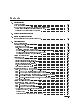
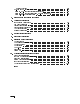
Contents 1. Getting Started What Is Servicing? . . . . . . . . . . . . . . . . . . . When Is Servicing Needed? . . . . . . . . . . . . . . . If You Want Hewlett-Packard to Service Your Color Display Determining Your Color Display's Serial Number . . . . Returning Your Color Display for Service . . . . . . . . . . . . . . . . . . . . . . . . . . . . . . . . . . . . . . . . . . . . . . . . . . . . . . . . . . . . . . 1-2 1-2 1-3 1-3 1-5 3.
Service Test List . . . . . . . . . . . . . . . . . . HP-MSIB and HP-IB Troubleshooting . . . . . . . . . . State 10. HP-MSIB Fault Indicator Light is Lit. . . . . . State 11. HP-MSIB Troubleshooting, HP-MSIB Light is O State 12. HP-IB Troubleshooting . . . . . . . . . . . . . . . . . . . . . . . . . . . . . . . . . . . . . . . . . . . . . . . . . . . . . . . . . . . . . . . . . . 4-41 4-47 4-48 4-50 4-53 5. Recommended Test Equipment Tables 6.
Figures 1-1. 4-1. 4-2. 4-3. 4-4. 4-5. 4-6. 4-7. 4-8. 4-9. 4-10. 6-1. 6-2. 6-3. 6-4. 6-5. 9-1. 9-2. 9-3. 9-4. 9-5. 9-6. 9-7. 9-8. 9-9. 10-1. 10-2. 10-3. 10-4. Typical Serial Number Label . . . . . . . . . . . . . . . Static-Safe Work Station . . . . . . . . . . . . . . . . . Overall Block Diagram of Color Display . . . . . . . . . . A5 Processor Diagnostics Location . . . . . . . . . . . . A4 Power Supply Indicators and Fuses (Front) . . . . . . . A4 Power Supply Indicators and Fuses (Back) . . . . . . .
1 Getting Started This chapter provides information to help get you started so that your color display is serviced properly. This chapter answers the questions \What Is Servicing?" and \When Is Servicing Needed?". It then describes the procedures used to return your color display to Hewlett-Packard for servicing.
What Is Servicing? Servicing includes testing, adjusting, calibrating, troubleshooting, and repairing. There are di erent categories of testing available. These categories are module veri cation tests, system veri cation of operation tests, and system performance tests. Module Module veri cation tests are used to test modules so that when assembled Veri cation Tests into a system, the system meets the system's speci cations. These sets of tests are used during servicing.
If You Want Hewlett-Packard to Service Your Color Display Before calling Hewlett-Packard or returning your color display for service, please read your warranty information. Warranty information is printed at the front of this service guide. In any correspondence or telephone conversations, refer to the color display by its full model number and full serial number. With this information, the Hewlett-Packard representative can determine whether your unit is still within its warranty period.
Table 1-1. Hewlett-Packard Sales and Service O ces US FIELD OPERATIONS HEADQUARTERS Hewlett-Packard Company 19320 Pruneridge Avenue Cupertino, CA 95014, USA (800) 752-0900 California Hewlett-Packard Co. 1421 South Manhattan Ave. Fullerton, CA 92631 (714) 999-6700 EUROPEAN OPERATIONS HEADQUARTERS Hewlett-Packard S.A. 150, Route du Nant-d'Avril 1217 Meyrin 2/Geneva Switzerland (41 22) 780.8111 Hewlett-Packard Company 3495 Deer Creek Rd.
Returning Your Color Display for Service Hewlett-Packard has sales and service o ces around the world to provide complete support for your color display. To obtain servicing information or to order replacement parts, contact the nearest Hewlett-Packard sales and service o ce listed in Table 1-1. Use the following procedure to return your color display to Hewlett-Packard for service: 1. Fill out a service tag (available at the end of this service guide) and attach it to the instrument.
Table 1-2.
2 Module Veri cation Software Module Veri cation Software is a program that is designed to automate module veri cation tests and adjustment procedures. Note The HP 70004A color display does not have any automated module veri cation tests and therefore does not use module veri cation software. The HP 70004A color display's tests and adjustment procedures are not automated; they require the user to perform step-by-step manual procedures.
3 Before Extensive Servicing This chapter contains information to help identify and resolve some common problems that may occur with your color display before extensive servicing. Symptoms to various problems are listed at the top of each page. Most symptoms have a brief description or explanation to help provide more insight into their cause. A possible cause for the symptom and a checklist of possible solutions are then presented. Use this checklist as an aid to correct the problem.
If an E is Flashing in the Display Status Box On power-up, the E in the display status box will ash if the external HP-MSIB loop is not yet ready. The ashing E will stop when the external loop is established. No error messages are displayed. The ashing E fault indicator light in the display status box performs a similar function as the ashing ERR fault indicator on HP 70000 Series modular spectrum analyzer system.
4 Troubleshooting This chapter contains information about troubleshooting your color display. It presents information on preparing a static-safe work station and then it presents a set of troubleshooting procedures that can be used to optimize repair time. Safety Considerations This instrument has been designed in accordance with international safety standards.
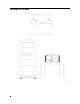
Preparing a Static-Safe Work Station Electrostatic discharge (ESD) can damage or destroy electronic components. Therefore, all work performed on assemblies consisting of electronic components should be done at a static-safe work station. Figure 4-1 shows an example of a static-safe work station. Two types of ESD protection are shown: a conductive table mat and wrist strap combination a conductive oor mat and heel strap combination Figure 4-1.
Reducing ESD Damage To help reduce the amount of ESD damage that occurs during testing and servicing use the following guidelines: Be sure that all instruments are properly earth-grounded to prevent buildup of static charge. Personnel should be grounded with a resistor-isolated wrist strap before touching the center pin of any connector and before removing any assembly from a piece of equipment.
If Display-Disruptive Errors Occur Display-disruptive errors are those that interfere with normal display operation and error reporting. The testing will stop at the rst failed test.
If Display-Disruptive Errors Occur A5 ROM (U23) CHECKSUM A5 ROM (U24) CHECKSUM A5 ROM (U25) CHECKSUM A5 ROM (U26) CHECKSUM A5 8041 INTERFACE A5 GRAPHICS DRAM A5 GRAPHICS VRAM A test of CMOS RAM has failed. The data in CMOS RAM is read, saved, and complemented. Every other address is then tested to see if the data is unchanged. To solve this problem: 1. Replace the A5 processor.
If Display-Disruptive Errors Occur 1. Replace the A5 processor. A5 GRAPHICS PROCESSOR A5DS2 LED Pattern: This display-disruptive error occurs when the processor on the A5 processor recieves an unrecognizable command. A test of the Graphics Processor System has failed. The processor has attempted to read and verify the contents of a location in the graphics system DRAM. The GSP loads this location with a known pattern during its initialization. To solve this problem: 1.
If Hardware-Warning Errors Messages (6000 {6999) Occur If Hardware-Warning Errors Messages (6000 {6999) Occur The A5 RAM memory failed a checksum test. 6002 A5 RAM Checksum (battery?) To solve this problem: 1. Cycle the line power to try and clear the error. 2. Replace the battery BT1 located on the A5 processor. 3. If the problem persists, replace the A5 processor. (Refer to Chapter 9.
If Hardware Error Messages (7000{7999) Occur Hardware errors are generated when a module in the HP 70000 Series modular spectrum analyzer system is not working properly. These errors can occur at any time. Hardware errors range from 7000{7999. One or more of the following hardware error messages may appear on your system display: 7038 A5 Error in 8041 This hardware error occurs when communications fail between the A5 8041 processor and the main processor.
If Hardware Error Messages (7000{7999) Occur 7063 7064 7065 7066 A5 ROM (U24) Checksum A5 ROM (U26) Checksum A5 ROM (U23) Checksum A5 ROM (U25) Checksum 7090 A5 Graphics DRAM error 7091 A5 Graphics VRAM error 7092 A5 Graphics Processor This hardware error occurs when a checksum is calculated on all ROMs. To solve this problem: 1. Replace the defective ROM. 2. If the problem persists, replace the A5 processor. 3. If necessary, obtain service from Hewlett-Packard.
Overall Block Diagram of Color Display Figure 4-2.
Display Troubleshooting DANGER These procedures require access to the interior of the color display, only quali ed service personnel should perform the servicing procedures. Use electrostatic discharge (ESD) precautions when performing any servicing. Do not touch the A4 power supply with your hands while power is applied. The A4 power supply has lethal voltages, with lethal currents, in all areas for at least three minutes after power is turned o .
Figure 4-3. A5 Processor Diagnostics Location The instrument can be conceptually divided into three parts: a power supply function, a display function, and an HP-MSIB control function. With this division in mind, troubleshooting can be performed sequentially, beginning with the power supply function. This procedure is divided into three corresponding sections. If the power supply is known to be operating properly, skip to the next section.
Diagnostic Tools There are a number of diagnostic tools built into the color display to aid in troubleshooting. These are described as follows: A4 Power Supply Diagnostic Tools Several indicators aid in determining the operating condition of the power supply. These are: Front-Panel Lights Internal Lights Fan Operation Module Operation For descriptions of these tools, refer to \Troubleshooting the A4 Power Supply".
The Key Test may be initiated by the user at any time. This is done using the misc , display tests , KEY TEST softkeys. This test allows each front panel key to be tested. Detailed instructions are placed on the screen. Each key is veri ed by displaying a description of the key pressed. The left arrow, or backspace, key is veri ed and then causes the test program to exit. The Knob Test may be initiated by the user at any time. This is done using the misc , display tests , KNOB TEST softkeys.
5. Press ENTER . NNNNNNNNNNNNNNNNN Table 4-3. Decimal/Hexadecimal Conversion Decimal Hexadecimal Decimal Hexadecimal 0 1 2 3 4 5 6 7 8 9 10 11 12 13 14 15 0 1 2 3 4 5 6 7 8 9 A B C D E F 16 17 18 19 20 21 22 23 24 25 26 27 28 29 30 31 10 11 12 13 14 15 16 17 18 19 1A 1B 1C 1D 1C 1D The HP-MSIB Utility key begins a utility for managing HP-MSIB directly. The HP-MSIB utility is intended for use during the development of new modules. This utility interferes with the normal system operation.
Troubleshooting the A4 Power Supply DANGER These procedures require access to the interior of the color display, only quali ed service personnel should perform the servicing procedures. Use electrostatic discharge (ESD) precautions when performing any servicing. Do not touch the A4 power supply with your hands while power is applied. The A4 power supply has lethal voltages, with lethal currents, in all areas for at least three minutes after power is turned o .
Figure 4-4.
Figure 4-5.
Potential A4 power supply failures may be categorized as follows: State 1. No Observed Power. The Front-Panel Indicator is o . State 2. The FAULT Indicator Light (A4DS6) is Lit. State 3. The I-LIMIT Fault Indicator Light (A4DS5) is Lit. State 4. Front-Panel LINE Indicator is O . Modules Have Power. State 5. Normal Operation Except Display is Blank. State 6. Front-Panel Indicators Normal, No Module Power. Note Some fault indicators may be eliminated by adjustments.
State 1. No Observed Power. The Front-Panel Power Indicator is O . If the input voltage is 230 Vac, but the voltage selector switch is set for 115 Vac Note (see to Figure 4-6), the input fuse is blown at turn on, protecting the display. Figure 4-6. Voltage Selector Switch Use a line cord that is known to be good. Verify that the input line voltage is within limits and that the display voltage selector switch setting agrees with the input line-voltage.
Use of a Ground Fault Interrupter (GFI), a Line-Isolated Variable Mains Transformer (VARIAC), and extreme care are mandatory when servicing the A4 power supply. Service personnel must use a >>1 M resistor-isolated wrist strap or heel strap while handling the A4 power supply. To avoid damaging the HP 70004A color display module connectors, the HP 70004A color display must be o before installing or removing any modules. 2.
If the problem is not xed, a troubleshooting clue was missed and more thorough troubleshooting is required.
State 2. The FAULT Indicator Light (A4DS6) is Lit. Some fault indicators may be eliminated by adjustments. Note To determine if this is the correct state to troubleshoot, remove the instrument cover. Refer to Figure 4-4 and Figure 4-5 for the location of the test points and indicators discussed below. Verify that the voltage at A4TP3 is approximately 5 V. If it is not, return to \State 1." If the indicator labeled I LIMIT is on, skip to \State 3." If the indicator labeled FAULT is on, proceed with \State 2.
DANGER These procedures require access to the interior of the color display, only quali ed service personnel should perform the servicing procedures. Use electrostatic discharge (ESD) precautions when performing any servicing. Do not touch the A4 power supply with your hands while power is applied. The A4 power supply has lethal voltages, with lethal currents, in all areas for at least three minutes after power is turned o .
Transformer (VARIAC) and check the A4DS6 FAULT indicator to see if the supply is now working. b. If the supply is now working, the problem is likely a short on one of the assemblies using the +5 Vdc supply. Isolate the fault to the A5 processor, the A6 HP-MSIB or the A2 interface by connecting them one at a time. c. If the supply is still not working, the problem is likely in the switching power supply. Additional troubleshooting information is located in the \Component-Level Hints".
State 3. The I LIMIT Fault Indicator Light (A4DS5) is Lit. Some fault indicators may be eliminated by adjustments. Note To determine if this is the correct state to troubleshoot, remove the instrument cover. Refer to Figure 4-4 and Figure 4-5 for the location of test point and indicators discussed below. Verify that the voltage at A4TP3 is approximately 5 V. If it is not, return to \State 1." If the indicator labeled FAULT is lit, return to \State 2.
b. If the I LIMIT indicator (A4DS5) is o and the power supply begins operating, verify the voltages between the following test points: A4TP24 +65V to A4TP25 +65VR A4TP26 +5VS to A4TP27 +5VRS A4TP23 +18V to A4TP29 +12VR A4TP28 +12V to A4TP29 +12VR A4TP22 012V to A4TP29 +12VR If the voltages are within 65%, a short probably exists on one or more of the following: the W3, the A5 processor, the A6 HP-MSIB, or the A2 interface. Turn the Line-Isolated Variable Mains Transformer (VARIAC) o .
State 4. Front-Panel LINE Indicator is O . Modules Have Power. This condition is most likely caused by a failure in the 5 V supply of the display. This supply is connected to the front panel LINE indicator and is used by both the A5 processor and A6 HP-MSIB. In this state, any installed modules should have power, but since the HP-MSIB will not be functioning, the error (ERR) indicator on each module should blink.
State 5. Normal Operation Except Display is Blank. This state normally means the +65 V power supply is not working. This supply is located on the A4 power supply. The supply passes through the A5 processor to the A3 monitor/monitor bracket. The A5 processor is capable of shutting down (turning o ) the +65 V supply. Any keystroke turns the +65 Vdc back on. This should be done rst to insure the problem is hardware. Allow at least one minute for the monitor to warm up.
If this voltage is approximately 65 V, the problem is either the ribbon cable W3, the A5 processor or the A3 monitor/monitor bracket. Continue with step 3. d. There is either a short or an open in the +65 Vdc system. To isolate the faulty assembly, disconnect W3, A5 processor, W4, and A3 monitor/monitor bracket. Reconnect W3, A5 processor, W4, and A3 monitor/monitor bracket one at a time, check A4F701 or the voltage between A4TP24 +65V and A4TP25 +65VR.
State 6. Front-Panel Indicators Normal, No Module Power. The display supplies the power requirements of the modules. This state presumes that the 40 kHz supply is working, because the front panel indicators are normal. The front panel LINE indicator is powered by the +5 V supply, which is derived from the 40 kHz system. The 40 kHz power is generated on the A4 power supply. It is routed out connector A4P1, through W3 ribbon cable, to the A5 processor, coming in on connector A5J1.
touch the power supply while power is applied. Verify the display's voltage selector switch setting (115 Vac). b. Using a DVM, check the voltage between pins 37/39 and 38/40 on A5J5 for a reading of approximately 27 Vac. c. If the voltage on A5J5 is good, the problem is likely on the A6 assembly. This can be veri ed by checking the continuity between the corresponding pins of A6J7 and the pins on each of A6J3 through A6J6. Replacing the A6 assembly should correct the problem. d.
Display and Processor Troubleshooting This section is to assist with determining which assembly, the A3 monitor/monitor bracket or the A5 processor, needs replacing. It is assumed that all power supplies are working properly. Some additional information is provided to assist in component-level troubleshooting of the A5 processor. There are no eld-serviceable parts in the A3 monitor/monitor bracket. Potential display and processor failures may be categorized as below: State 7. Display-Disruptive Message.
State 9. Memory Card Troubleshooting. Memory Card information is controlled by the A5 processor. The A2 interface provides a path for control and data signals, plus the connector for the Memory Card. 1. Press 4Display5, 4Mass Storage5, 4MSI5, and 4Memory Card5. The amber light next to the memory card slot should blink. If the red light is on, then the battery in the memory card needs to be replaced.
A5S1 ADDR SW: 0NNNN101 CONTINUE MODE: 0NNNN111 HALT MODE: Does not display error message, repeats test continuously. LEDs ash once per completion of test loop. If the display system functions, the test name is displayed in block letters on the monitor and re-written once per completion of test loop. Displays error message, halts test on error. LEDs display error code. LEDs ash once per completion of test loop.
Table 4-5 lists the description of each of the Select Mode Tests. The test number shown is used in place of the NNNN in the A5S1 ADDR SW. Table 4-5. Test Descriptions Name Test Number 0 0000 LEDs 1 2 0001 0010 ROM Checksum CMOS RAM Data 3 0011 CMOS RAM Address 4 0100 Slave Processor 8041 5 0101 DRAM Address 6 0110 VRAM Address 4-36 Troubleshooting Description To visually verify LED operation, segments of the LED displays, A5DS1 and A5DS2, are ashed alternately on and o .
Test Number Table 4-5. Test Descriptions (continued) Name Description 7 0111 HP-MSIB 8 1000 HP-HIL 8042 9 1001 Real Time Clock 10 1010 Memory Card LED Check The functions performed are: send a NULL to Address 31 and check for NMAA (No Module At Address),which is the expected response. Send 0, 1, 2, 4, 8, 16, 64, 128 to self and check the data after each is sent.
Service Tests These tests are intended to assist in component-level fault isolation. They require the display system cover to be removed and the processor board be placed into the service position to allow system operation and access to the component side of the board. DANGER CAUTION These procedures require access to the interior of the color display, only quali ed service personnel should perform the servicing procedures. Use electrostatic discharge (ESD) precautions when performing any servicing.
6. If the above steps are good, the processor kernel is functioning properly without the ROMs. The ROM Checksum Select Mode Test will help verify proper ROM operation. Troubleshooting LEDs and DIP Switch Map The two 8 bit dip switches allow manual input of test codes and data. A5DS1 and A5DS2, ten segment LED displays (see Figure 4-7), are used to indicate test status and data. The RST push button switch, A5S4, allows the processor board to be reset to a power-up condition without cycling power.
Figure 4-8.
Service Test List Group 0 A5S1 ADDR SW: 110001X1 Group 0: A5S2 UPPER SW: 11111111 Test 0: 11111110 1111110X Test 1: Test 2: 111110XX 11110XXX Test 3: Test 4: 1110XXXX Test 5: 110XXXX0 Test 6: 10XXXXX0 Test 7: RAM strobes, RAM tests, External bus tests, Real Time Clock test, RAM and Real Time Clock battery backup tests. RAM strobes. Upper and lower byte write, word write, and word read. RAM data. Rotate bit pattern through RAM. RAM address.
Group 1 A5S1 ADDR SW: 11001101 Group 1: A5S2 UPPER SW: 11111111 Test 0: 11111110 Test 1: 1111110X Test 2: 111110XX Test 3: 11110XXX Test 4: 1110XXXX 110XXXXX Test 5: Test 6: 10XXXXXX Test 7: 0XXXXXXX Test 8: LEDs, dip switches, con guration bits, and 8041 functions. LEDs. Flash LEDs alternate bytes, upper and lower, then alternate bits. Dip switches. Read dip switch bits and write bit pattern to LEDs. (Switch open gives LED o , switch closed gives LED on.) I/O strobe veri cation.
Group 2 A5S1 ADDR SW: 110101X1 Group 2: A5S2 UPPER SW: 11111111 Test 0: 11111110 Test 1: 1111110X Test 2: 111110XX Test 3: 11110XXX Test 4: 1110XXXX Test 5: 110CTTTT Test 6: Graphics processor memory, video, and monitor test patterns. GSP DRAM and VRAM strobes. Read dip switches and write data pattern to rst location in DRAM and VRAM. G-test is strobed once per cycle as a scope trigger. GSP DRAM. Write to the DRAM, all addresses, with a low data bit rotated through all high bits.
Group 2 (continued) 10 Test 7: Dots, 17 X 9, superimposed on Tests 3 through 6 above. For grey tones, dots are white. For colors, dots are color #15. Note: Dots will have black or background color dots immediately above and below them in a four dot vertical group. These will be apparent when a black or the background color is not used to ll the screen. Pattern Key: 10000000 = 17 X 9 white dots on black screen. 1000GGGG = 17 X 9 white dots on grey #GGGG screen.
Group 3 A5S1 ADDR SW: 110101X1 Group 3: A5S2 UPPER SW: 11111111 Test 0: 11111110 Test 1: 1111110X Test 2: 111110XX Test 3: 11110XXX Test 4: HP-IB 9914 HP-IB data bus transmission. Setup HP-IB 9914 as a controller and transmit alternating data bit patterns on HP-IB data bus. Note: Remove all other HP-IB devices from the bus before using this test. An HP 59401A bus system analyzer must be plugged on the bus with REN o , LISTEN on, and FAST on. Data pattern will alternate from U125 to U252.
Group 4 A5S1 ADDR SW: 111001X1 Group 4: A5S2 UPPER SW: 11111111 Test 0: 11111110 Test 1: 1111110X 111110XX Test 2: Test 3: 11110XXX Test 4: 1110XXXX Test 5: 110XXXXX 10XXXXXX Test 6: Test 7: Interrupt tests, uses RAM for stack so RAM must be good. Not used. HP-HIL Shift-Reset NMI (requires HP-HIL keyboard). Turns LEDs o then on when Shift-Reset is pressed. 8041 timer interrupt. Sets up and services 8041 timer interrupts. HP-HIL timer or key interrupt (HP-HIL keyboard optional).
HP-MSIB and HP-IB Troubleshooting This section documents troubleshooting information for the communication part of the instrument. There are two types of communication supported: HP-IB HP-MSIB The Hewlett Packard Interface Bus (HP-IB) is used for control of instruments from system controllers. Most of the HP 70000 Series modular spectrum analyzer system do not use HP-IB internally. However, many of the systems will respond to HP-IB control.
State 10. HP-MSIB Fault Indicator Light is Lit. This light indicates a problem on the HP-MSIB External Loop or low bias (+5V) to the A6 HP-MSIB. The A6 HP-MSIB has a circuit that checks to see if the external cables are connected properly. This circuit also monitors the external HP-MSIB instruments to see if they are in RESET. Whenever an instrument connected to the HP-MSIB is turned o , all other instrument's I/O or HP-MSIB lights will turn on and all displays will be blanked. 1.
Figure 4-9.
State 11. HP-MSIB Troubleshooting, HP-MSIB Light is O . The use of a good display or master module, and good HP-MSIB cables are Note required for HP-MSIB troubleshooting. The ashing E fault indicator light in the display status box performs a similar function as the ashing ERR fault indicator on HP 70000 Series modular spectrum analyzer system series modules.
7. If the E or ERR light is still ashing, then the +5 V HP-MSIB supply on the A4 power supply may be too low. DANGER These procedures require access to the interior of the color display, only quali ed service personnel should perform the servicing procedures. Use electrostatic discharge (ESD) precautions when performing any servicing. Do not touch the A4 power supply with your hands while power is applied.
c. The above steps should have located the problem. If the problem still cannot be identi ed, the \HP-MSIB Diagnostic Tools" may be helpful. Figure 4-10.
State 12. HP-IB Troubleshooting The path for HP-IB signals from the HP-IB connector on the display rear panel to the modules consists of traces only (no cabling). The signals go from the HP-IB cable connector to the A6 HP-MSIB, then to the the A5 processor and to the module slots. All the module slots are connected in parallel on the A6 HP-MSIB. Note The most common cause of problems with dumping from the display to either a plotter or printer using HP-IB is a di erence in HP-IB settings.
5 Recommended Test Equipment Tables Table 5-1.
6 Adjustment Procedures This chapter contains the setups for all adjustment procedures that are used to optimize module performance when assemblies are changed, repaired, or adjusted. The HP 70004A color display adjustments are not automated; they require the user to perform step-by-step manual procedures. A procedure is considered an adjustment when the cover plate of a module must be removed to perform a repair or an adjustment. A procedure is also considered an adjustment when a module is replaced.
Power Supply Adjustments DANGER These procedures require access to the interior of the color display, only quali ed service personnel should perform the servicing procedures. Use electrostatic discharge (ESD) precautions when performing any servicing. Do not touch the A4 power supply with your hands while power is applied. The A4 power supply has lethal voltages, with lethal currents, in all areas for at least three minutes after power is turned o .
Power Supply Adjustments The purpose of the \Power Supply Adjustments" is to adjust the A4 power supply. Table 6-1 lists the adjustable components by reference designator, name, and adjustment description. 1. Remove the four screws securing the instrument cover at the rear of the HP 70004A color display and slide the instrument cover o . 2. Position the HP 70004A color display top-side-down on the work bench and remove the nine screws securing the A4 power supply.
Low Line Adjustment DANGER WARNING These procedures require access to the interior of the color display, only quali ed service personnel should perform the servicing procedures. Use electrostatic discharge (ESD) precautions when performing any servicing. Do not touch the A4 power supply with your hands while power is applied. The A4 power supply has lethal voltages, with lethal currents, in all areas for at least three minutes after power is turned o .
Low Line Adjustment Figure 6-1.
Low Line Adjustment The purpose of this adjustment procedure is to adjust the trip point of the line voltage sense circuit for power supply start-up. When the range switch is set to 115 V, the trip point is equivalent to 86 Vac. When the range switch is set to 230 V, the trip point is equivalent to 172 Vac. These are the lower limits for operation of the supply. 1. Remove the A4F1 service fuse from the power supply board. 2. Connect a set of insulated test leads and clips (600 V insulation) to the DVM.
Current Limit Adjustment Current Limit Adjustment DANGER These procedures require access to the interior of the color display, only quali ed service personnel should perform the servicing procedures. Use electrostatic discharge (ESD) precautions when performing any servicing. Do not touch the A4 power supply with your hands while power is applied. The A4 power supply has lethal voltages, with lethal currents, in all areas for at least three minutes after power is turned o .
Current Limit Adjustment The purpose of this adjustment procedure is to set the current trip point for the 40 kHz output. Module load currents exceeding the current trip point cause the 40 kHz output to shut down, preventing damage to the A4 power supply. 1. Increase the Line-Isolated Variable Mains Transformer (VARIAC) output until the DVM reads 325 Vdc 610 Vdc. Turn the Line-Isolated Variable Mains Transformer (VARIAC) o and wait one minute or more after A4DS1 goes out. 2.
Output Voltage Adjustment Output Voltage Adjustment DANGER These procedures require access to the interior of the color display, only quali ed service personnel should perform the servicing procedures. Use electrostatic discharge (ESD) precautions when performing any servicing. Do not touch the A4 power supply with your hands while power is applied. The A4 power supply has lethal voltages, with lethal currents, in all areas for at least three minutes after power is turned o .
Output Voltage Adjustment The purpose of this adjustment procedure is to adjust the output voltage of the regulated 40 kHz sine wave provided to the modules. 1. Turn the Line-Isolated Variable Mains Transformer (VARIAC) o . Wait one minute or more after A4DS1 goes out, then connect the DVM positive lead to A4TP20 (V0) and the negative lead to A4TP2 (COM). 2. Reinsert the A4F1 Service Fuse. Turn the Line-Isolated Variable Mains Transformer (VARIAC) on.
+65 Volt Adjustment +65 Volt Adjustment DANGER These procedures require access to the interior of the color display, only quali ed service personnel should perform the servicing procedures. Use electrostatic discharge (ESD) precautions when performing any servicing. Do not touch the A4 power supply with your hands while power is applied. The A4 power supply has lethal voltages, with lethal currents, in all areas for at least three minutes after power is turned o .
+65 Volt Adjustment The purpose of this adjustment procedure is to adjust the +65 Vdc output voltage that provides power to the monitor. 1. Connect the DVM between TP24, +65V, and TP25, +65R. Test point TP25 is accessed by clipping to the lead of R709. 2. Turn the Line-Isolated Variable Mains Transformer (VARIAC) on. Adjust the Line-Isolated Variable Mains Transformer (VARIAC) to 115 Vac. Check for operation to verify that the power supply is functioning. 3. Adjust R728 until the DVM reads 65.05 Vdc 60.
Monitor Adjustments Monitor Adjustments DANGER These procedures require access to the interior of the color display, only quali ed service personnel should perform the servicing procedures. Use electrostatic discharge (ESD) precautions when performing any servicing. Do not touch the A4 power supply with your hands while power is applied. The A4 power supply has lethal voltages, with lethal currents, in all areas for at least three minutes after power is turned o .
Monitor Adjustments The purpose of this adjustment procedure is to perform the Vertical Centering Adjustment and the Display Intensity Adjustment. Vertical Centering Adjustment Vertical Centering Adjustment aligns the entire display simultaneously. 1. Turn the power to the HP 70004A color display on. 2. Press 4DISPLAY5. 3. Adjust the Vertical Centering Adjustment on the monitor until the displayed softkey menus are properly aligned with their corresponding keys.
7 Module Veri cation Tests This chapter would have contained the setups for all module veri cation tests that must be performed in order to optimize module performance when assemblies are changed, repaired, or adjusted. Note The HP 70004A color display does not have any module veri cation tests.
8 Equipment Calibration This chapter would have contained the setups for all equipment calibration procedures that must be performed in order to optimize module performance when assemblies are changed, repaired, or adjusted. Note The HP 70004A color display does not have any equipment calibration procedures.
9 Replacing Major Assemblies This chapter contains procedures for removal and replacement of major assemblies in your color display. Instructions are given for the following assemblies: \A1 Front Panel" \A3 Monitor/Monitor Bracket" \A4 Power Supply" \A5 Processor" \A6 HP-MSIB" \Rear Frame" \Custom Key-Panel Assembly" The words \right" and \left" are used throughout the replacement procedures to indicate the sides of the display as viewed from the front panel.
A1 Front Panel DANGER These procedures require access to the interior of the color display, only quali ed service personnel should perform the servicing procedures. Use electrostatic discharge (ESD) precautions when performing any servicing. Do not touch the A4 power supply with your hands while power is applied. The A4 power supply has lethal voltages, with lethal currents, in all areas for at least three minutes after power is turned o .
A1 Front Panel To Replace the A1 Front Panel 1. 2. 3. 4. 5. 6. 7. 8. Reconnect the ribbon cable to the A1 front panel. Insert the right side of the A1 front panel rst. While holding the right side in place, insert the left side. Secure the A1 front panel to the monitor using four screws (3). Secure the A1 front panel to the front frame using two screws (2). Tighten the four screws (1) on the top side of the monitor. Replace the instrument cover. Reconnect the line cord. Figure 9-1.
A3 Monitor/Monitor Bracket DANGER These procedures require access to the interior of the color display, only quali ed service personnel should perform the servicing procedures. Use electrostatic discharge (ESD) precautions when performing any servicing. Do not touch the A4 power supply with your hands while power is applied. The A4 power supply has lethal voltages, with lethal currents, in all areas for at least three minutes after power is turned o .
A3 Monitor/Monitor Bracket CAUTION Damage to the eighty-pin connector will result if the free end of the A5 processor is lifted beyond the necessary height. Do not lift higher than required for the A5 processor connectors to clear the main deck. 9. Carefully lift the free side of the A5 processor (side closest to A4 power supply) and disconnect it from the A6 HP-MSIB. 10. Position the A5 processor onto the A4 power supply with the component side facing up. 11. Disconnect W1 from A5J2 and W4 from A5J3.
A3 Monitor/Monitor Bracket Figure 9-2.
A3 Monitor/Monitor Bracket Figure 9-3.
A3 Monitor/Monitor Bracket A4 Power Supply DANGER These procedures require access to the interior of the color display, only quali ed service personnel should perform the servicing procedures. Use electrostatic discharge (ESD) precautions when performing any servicing. Do not touch the A4 power supply with your hands while power is applied. The A4 power supply has lethal voltages, with lethal currents, in all areas for at least three minutes after power is turned o .
A4 Power Supply CAUTION 7. 8. 9. 10. Before positioning the A4 power supply onto the A5 processor, ensure that the insulator (mounted on the trace-side of the A4 power supply) is placed between the two assemblies. Position the A4 power supply onto the A5 processor with the component side facing up. Disconnect the line cable from A4P2. Disconnect W3 from A4P1. Remove the A4 power supply. To Replace the A4 Power Supply 1. 2. 3. 4. 5. 6. 7. 8.
A4 Power Supply Figure 9-4.
A5 Processor A5 Processor DANGER These procedures require access to the interior of the color display, only quali ed service personnel should perform the servicing procedures. Use electrostatic discharge (ESD) precautions when performing any servicing. Do not touch the A4 power supply with your hands while power is applied. The A4 power supply has lethal voltages, with lethal currents, in all areas for at least three minutes after power is turned o .
A5 Processor 7. Carefully lift the free side of the A5 processor (side closest to A4 power supply) and disconnect it from the A6 HP-MSIB. 8. Position the A5 processor onto the A4 power supply with the component side facing up. 9. Disconnect W1 from A5J2, W2 from A5J4, W3 from A5J1, W4 from A5J3, and the fan cable from A5J9. 10. Remove the A5 processor. To Replace the A5 Processor 1. Position the A5 processor onto the A4 power supply with the component side facing up. 2.
A5 Processor Figure 9-5.
A6 HP-MSIB DANGER These procedures require access to the interior of the color display, only quali ed service personnel should perform the servicing procedures. Use electrostatic discharge (ESD) precautions when performing any servicing. Do not touch the A4 power supply with your hands while power is applied. The A4 power supply has lethal voltages, with lethal currents, in all areas for at least three minutes after power is turned o .
A6 HP-MSIB 13. Remove the two screws (6) securing the A6 HP-MSIB to the rear frame. 14. Remove the A6 HP-MSIB. To Replace the A6 HP-MSIB 1. 2. 3. 4. 5. 6. 7. 8. 9. 10. 11. 12. Secure the A6 HP-MSIB to the rear frame using two screws (6). Press the HP-IB connector side of the rear panel into place rst. Secure the HP-MSIB connectors using four hex screws (5). Secure the HP-IB connector using two hex screws (4). Replace the two athead screws (3).
A6 HP-MSIB Figure 9-6.
Rear Frame Rear Frame DANGER These procedures require access to the interior of the color display, only quali ed service personnel should perform the servicing procedures. Use electrostatic discharge (ESD) precautions when performing any servicing. Do not touch the A4 power supply with your hands while power is applied. The A4 power supply has lethal voltages, with lethal currents, in all areas for at least three minutes after power is turned o .
Rear Frame Custom Key-Panel Assembly The custom keypad allows an operator to access or activate unique system functions from the front of the HP 70004A color display. To Remove the Key Panel 1. There are two di erent release mechanisms for the blank panel. If the blank panel has a slot in the right-hand side, insert a slotted screwdriver into the slot (1) as shown in Figure 9-8. Gently pry the screwdriver's handle to the left and the blank panel (2) should snap out. 2.
Custom Key-Panel Assembly Figure 9-9.
10 Overall Parts Identi cation Drawings This chapter contains information on all overall parts identi cation drawings that should be used when performing the troubleshooting procedures descibed in this service guide.
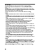
Front View Identi cation Overall Parts Identi cation Listing, Front View Item HP Part Number 1 2 3 4 5 6 7 8 9 10 11 12 13 14 15 16 17 18 19 20 21 22 23 24 25 26 27 28 0515-0846 70004-40011 70004-40012 70004-40016 70004-00023 70004-40001 70004-40009 5041-1835 5041-0808 5041-0819 5041-0855 5041-0855 5041-0811 5041-0812 5041-0813 5041-0814 5041-0815 5041-0816 5041-0817 5041-0818 5041-0816 70004-40011 0370-3069 70004-40003 70004-40010 1000-0860 0515-1012 70004-60020 70004-00011 C Qty D 5 4 5 9 4 2 0 4 9 2
Front View Identi cation Figure 10-1.
Top View of Monitor Identi cation Overall Parts Identi cation Drawing, Top View Item 2 3 4 5 6 7 HP Part Number 2090-0210 0515-1079 0515-0866 70004-20016 70004-00009 0515-1069 0515-1069 C Qty D 7 8 9 7 6 6 6 1 3 1 4 1 4 4 10-4 Overall Parts Identi cation Drawings Description Mfr Code Mfr Part Number A3 Monitor SCREW SMM3.0 8SEMPNPD SCREW SMM3.0 8CWPNPDS STANDOFF-MONITOR PLATE-ADAPTER SCREW SMM4.0 10SEMPNPD SCREW SMM4.
Top View of Monitor Identi cation Figure 10-2.
Rear View Identi cation Overall Parts Identi cation Drawing, Rear View Item HP Part Number 1 2 3 4 5 6 7 8 9 10 11 12 13 14 15 16 70004-00007 3160-0422 0515-1069 0515-1005 0515-0914 70004-20020 70004-20013 0515-1069 0515-0914 0380-1214 2190-0577 0515-1772 0515-0914 0380-2000 0515-1588 70004-40019 2110-0703 C Qty D 4 3 6 0 8 3 4 6 8 6 1 8 8 0 4 2 7 1 1 4 2 4 1 1 7 2 2 2 4 2 4 4 4 1 Description Mfr Code Mfr Part Number PANEL, REAR DRESS GRIL, FAN SCREW SMM4.0 10SEMPNPD SCREW SMM3.
Rear View Identi cation Figure 10-3.
Bottom View Identi cation Overall Parts Identi cation Listing, Bottom View Item HP Part Number 1 2 3 4 0515-0866 0515-0866 70004-40020 70004-00030 C Qty D 9 9 5 3 10 9 1 1 Description Mfr Code Mfr Part Number SCREW SMM3.0 8CWPNPDS SCREW SMM3.
Side View Identi cation Side View Identi cation Overall Parts Identi cation Listing, Side View Item HP Part Number 1 2 3 4 5 6 70004-20011 70004-00033 70004-40008 70004-00032 5041-8801 5041-8822 C Qty D 2 6 9 5 8 3 1 1 1 1 2 2 Description Mfr Code Mfr Part Number FRONT FRAME MAIN DECK MODULE GUIDE STRUT, SIDE FRONT BOTTOM FEET REAR BOTTOM FEET 28480 28480 28480 28480 28480 28480 70004-20011 70004-00033 70004-40008 70004-00032 5041-8801 5041-8822 Overall Parts Identi cation Drawing, Side View
A5 Processor Service View Identi cation Table 10-1. Overall Parts Identi cation Drawing, A5 Service View Item1 HP Part Number C Qty D Description Mfr Code Mfr Part Number 28480 28480 28480 28480 8710-1651 8120-1378 70800B 85700A ACCESSORIES SUPPLIED 8710-1651 8120-1378 70800B 85700A 4 1 5 3 1 1 2 1 8mm Ball Driver Power Cord MS-IB Cable 1M Card SRAM 32K B1 70004-00024 5 1 Fan Assembly (includes cable) FL1 70004-60019 4 1 Line Filter Assembly (includes cable) F1 2110-0703 7 1 Fuse, 6.
A5 Processor Service View Identi cation Figure 10-4.
Index A A1A1 keyboard, 9-2 A1A2 RPG, 9-2 A1 front panel removal/replacement, 9-2 A3 monitor/monitor bracket removal/replacement, 9-4 A4 power supply removal/replacement, 9-8 A5 processor removal/replacement, 9-11 A6 HP-MSIB removal/replacement, 9-14 adjustment, de nition, 6-1 adjustments +65 Volt Adjustment, 6-11 current limit adjustment, 6-7 low line adjustment, 6-4 monitor adjustments, 6-13 output voltage adjustment, 6-9 power supply adjustments, 6-2 B block diagram, 4-10 C custom key-panel assembly
V veri cation, of system operation tests, 1-2 Index-2