About this Manual We’ve added this manual to the Agilent website in an effort to help you support your product. This manual is the best copy we could find; it may be incomplete or contain dated information. If we find a more recent copy in the future, we will add it to the Agilent website. Support for Your Product Agilent no longer sells or supports this product. Our service centers may be able to perform calibration if no repair parts are needed, but no other support from Agilent is available.
Installation and Veri cation Guide HP 70300A RF Tracking Generator ABCDE HP Part No. 70300-90107 Printed in USA March 1995 Edition A.0.
Notice The information contained in this document is subject to change without notice. Hewlett-Packard makes no warranty of any kind with regard to this material, including, but not limited to, the implied warranties of merchantability and tness for a particular purpose. Hewlett-Packard shall not be liable for errors contained herein or for incidental or consequential damages in connection with the furnishing, performance, or use of this material. Restricted Rights Legend.
Certi cation Hewlett-Packard Company certi es that this product met its published speci cations at the time of shipment from the factory. Hewlett-Packard further certi es that its calibration measurements are traceable to the United States National Institute of Standards and Technology, to the extent allowed by the Institute's calibration facility, and to the calibration facilities of other International Standards Organization members.
Safety Symbols The following safety symbols are used throughout this manual. Familiarize yourself with each of the symbols and its meaning before operating this instrument. CAUTION The CAUTION sign denotes a hazard. It calls attention to a procedure which, if not correctly performed or adhered to, could result in damage to or destruction of the product or the user's work. Do not proceed beyond a CAUTION sign until the indicated conditions are fully understood and met.
General Safety Considerations WARNING The instructions in this document are for use by quali ed personnel only. To avoid electrical shock, do not perform any servicing unless you are quali ed to do so. The opening of covers or removal of parts is likely to expose dangerous voltages. Disconnect the instrument from all voltage sources while it is being opened. The power cord is connected to internal capacitors that may remain live for ve seconds after disconnecting the plug from its power supply.
Installation at a Glance vi
The HP 70300A RF tracking generator is a 2/8-width module designed to work in an HP 70000 Series modular measurement system. The HP 70300A RF tracking generator has a frequency range of 20 Hz to 2.9 GHz and is a slave module controlled by the HP 70900A/B local oscillator source. The output of the HP 70300A RF tracking generator tracks the tuned frequency of the spectrum analyzer (such as the HP 71210A microwave spectrum analyzer) with which it is used.
In This Book This book describes all of the installation procedures to properly install your tracking generator in an HP 70000 Series modular measurement system. Each module in the HP 70000 Series modular measurement system has its own installation guide. For further information related to the installation of additional and alternate modules that can be used in this system, refer to that module's installation guide or refer to the HP 70000 Modular Spectrum Analyzer Installation and Veri cation Manual.
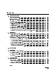
Contents 1. General Information Manual Conventions . . . . . . . . . . . . . . . . . . Safety Considerations . . . . . . . . . . . . . . . . . Initial Inspection . . . . . . . . . . . . . . . . . . . . Firmware Compatibility . . . . . . . . . . . . . . . . Accessories . . . . . . . . . . . . . . . . . . . . . . Front-Panel and Rear-Panel Features . . . . . . . . . . Front-Panel Status/Error LEDs . . . . . . . . . . . . Front-Panel Inputs and Outputs . . . . . . . . . . . . Module Latch . . . . . . . . . .
Figures 1-1. 1-2. 2-1. 2-2. 2-3. 2-4. HP 70300A RF Tracking Generator's Front-Panel and Rear-Panel Features . . . Typical Serial Number Label . . . . . . . . . . . . . . . . . . . . . . . . Address Map . . . . . . . . . . . . . . . . . . . . . . . . . . . . . . . HP 70300A RF Tracking Generator Address Switches . . . . . . . . . . . . . Module Installation in Mainframe . . . . . . . . . . . . . . . . . . . . . . HP 71100A Modular Spectrum Analyzer with an HP 70300A RF Tracking Generator . . . . . . . . . .
1 General Information Manual Conventions The following descriptions are used throughout this manual: Keys physically on an instrument are represented in the following way: Key . . . . . . . . . . . . . . . . . . . . . . . . . . . . . . . . . . . . . . . . . . . . . . . . . . . . . . . . . . . . . . . . . . . . . 4KEY5 Softkeys, keys de ned by software or rmware, are represented in the following way: Softkey . . . . . . . . . . . . . . . . . . . . . . . . . . . . . . . . . . . . . . . . . . . . . . . . . . .
Firmware Compatibility For the HP 70300A RF tracking generator to function properly, the HP 70900A/B local oscillator source must have a rmware version later than 850730. A rmware-upgrade kit is included when HP 70300A RF tracking generator Option 099 is ordered. Accessories The HP 70300A RF tracking generator may be ordered separately or as part of a precon gured HP 70000 Modular Measurement System.
Front-Panel and Rear-Panel Features Figure 1-1 shows the HP 70300A RF tracking generator's front-panel and rear-panel features. Front-Panel Status/Error LEDs All of the front panel status/error LEDs ash on, then o again, during the tracking generator's self-test. Listed below are the other reasons for each LED to light. For troubleshooting information, refer to Chapter 5. CAUTION When the AC COUPLED LED is lit, tracking generator damage may occur if the dc voltage level at the RF OUTPUT exceeds 25 V.
Front-Panel Inputs and Outputs Refer to Chapter 3, \Speci cations," for more information about the input and output characteristics. AM INPUT/OUTPUT This BNC (f) connector is the input and output for amplitude-modulating (AM) signals. When used as an input, the port's input impedance is 600 . An external source must be used to provide the AM input signal. When used as an output, the port's output impedance is 20 . At 400 Hz or 1 kHz, the AM output signal amplitude is nominally 1 V peak.
0|2.9 GHz OUT 0|2.9 GHz IN 300 MHz OUT 300 MHz IN 21.4 MHz IN SWEEP IN TUNE+SPAN IN HSWP IN Mainframe/Module Interconnect This SMA (f) connector normally connects to the 0|2.9 GHz IN connector. The 0-2.9 GHz OUT port is after the rst converter, but before the output attenuator and the normal ALC detector. This SMA (f) connector normally connects to the 0|2.9 GHz OUT connector. The signal available at this SMB (m) connector is the 300 MHz IN signal.
Figure 1-1.
If You Need to Contact Hewlett-Packard Before calling Hewlett-Packard or returning your tracking generator, please read your warranty information. Warranty information is printed at the front of this document. In any correspondence or telephone conversations, refer to the tracking generator by its full model number and full serial number. With this information, the Hewlett-Packard representative can determine whether your unit is still within its warranty period.
Table 1-2. Hewlett-Packard Sales and Service O ces US FIELD OPERATIONS EUROPEAN OPERATIONS HEADQUARTERS HEADQUARTERS Hewlett-Packard Company 19320 Pruneridge Avenue Cupertino, CA 95014, USA (800) 752-0900 California Hewlett-Packard S.A. 150, Route du Nant-d'Avril 1217 Meyrin 2/Geneva Switzerland (41 22) 780.8111 Hewlett-Packard Co. France 1421 South Manhattan Ave.
Returning Your Tracking Generator to Hewlett-Packard Hewlett-Packard has sales and service o ces around the world to provide complete support for your tracking generator. To obtain servicing information or to order replacement parts, contact the nearest Hewlett-Packard sales and service o ce listed in Table 1-2. Use the following procedure to return your tracking generator to Hewlett-Packard: 1. Fill out a service tag (available at the end of this service guide) and attach it to the instrument.
Table 1-3.
2 Installation This chapter contains information needed to install the HP 70300A RF tracking generator into an HP 70000 Series modular measurement system mainframe, and to check the basic operation of the tracking generator. Chapter 4 contains the tests needed to verify that the tracking generator meets its speci cations.
Addressing the Module The HP 70300A RF tracking generator needs an appropriate Hewlett-Packard Modular System Interface Bus (HP-MSIB) address to be able to communicate with the master of the HP 70000 Series modular measurement system. The HP 70300A RF tracking generator's HP-MSIB address is set using the tracking generator's ROW and COLUMN address switches. Determining the HP-MSIB Address The HP 70300A RF tracking generator has a factory-preset HP-MSIB address of 6, 19 (row 6, column 19).
Setting the HP-MSIB Address Switches The HP 70300A RF tracking generator's address switches are located on the top of the tracking generator. Table 2-1 gives the decimal value for each address switch when the switch is set to binary 1 (ON). Table 2-1. Decimal Equivalents of Row and Column Address Switches Address Switch Decimal Value Row 3* 2* 1 Column 4 2 1 5* 16 4 8 3 4 2* 2 1* 1 *These switches are factory-preset to binary 1 (ON), resulting in an HP-MSIB address of 6, 19 (row 6, column 19).
Installing the Module in the Mainframe The HP 70300A RF tracking generator needs to be installed in an HP 70000 Series modular measurement system mainframe before it will operate. Follow the procedure below to install the tracking generator into the mainframe. See Figure 2-3 for identi cation of the tracking generator and mainframe parts called out in the procedure. 1. Turn the mainframe LINE switch o . 2. Open the mainframe front panel door. 3. Slide the tracking generator into the mainframe. 4.
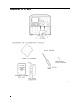
Connecting the Module-Interconnect Cables This section contains addressing and tracking generator-interconnect cabling information for the following system con gurations: HP 71100A modular spectrum analyzer with an HP 70300A RF tracking generator. HP 71210A microwave spectrum analyzer with both an HP 70300A RF tracking generator and an HP 70301A microwave tracking generator. In addition to the module-interconnect cables listed, system HP-MSIB cables must be connected.
Table 2-2.
Note Older HP 70300A RF tracking generators may have three additional connectors: 3.6214 GHz IN, 3.6214 GHz OUT, and LO OUT 3.0|6.6 GHz. When these connectors are present, use a jumper cable to connect 3.6214 GHz IN and 3.6214 GHz OUT together, and connect a 50 termination to LO OUT 3.0|6.6 GHz.
Figure 2-4.
HP 71210A Microwave Spectrum Analyzer with an HP 70300A RF Tracking Generator and an HP 70301A Microwave Tracking Generator To con gure an HP 70300A RF tracking generator and an HP 70301A microwave tracking generator into an HP 71210A microwave spectrum analyzer, connect the tracking generatorinterconnect cables according to the following list. The number in parentheses is the HP part number of the cable used for the connection.
Table 2-4. Cables and Adapters for an HP 71210A Microwave Spectrum Analyzer with HP 70300A RF Tracking Generator and HP 70301A Microwave Tracking Generator Description HP Part Number Quantity Required Semi-rigid, Type N Semi-rigid, LO I/O 5021-9319 5021-5449 5021-5495 Flexible, LO I/O HP 5061-9038 SMA 0.5 meter exible cable Flexible, System 5061-9015 5061-9016 5061-9017 5061-9018 5061-9019 5061-9020 Adapter, SMB tee (f)(m)(m) HP 1250-1391 50 SMB tee(f) (m) (m) 1 1 1 1 2 3 1 1 4 2 2 Figure 2-5.
Figure 2-6.
Checking Module Operation The operation of the HP 70300A RF tracking generator in an HP 70000 Series modular measurement system is veri ed by checking the results of the tracking generator's power-on self-test. Refer to Chapter 4 for tests that verify the tracking generator speci cations. The results of the self-test are determined by observing the front panel LEDs and by checking for error messages.
3 Speci cations This chapter contains characteristics and measurement-related speci cations. Table 3-1 lists the system speci cations and characteristics that are modi ed when the HP 70300A RF tracking generator is used in an HP 70000 Series modular measurement system spectrum analyzer con guration. For any system speci cations or characteristics not listed here, refer to the HP 70000 Modular Spectrum Analyzer Installation and Veri cation Manual.
Table 3-1. System Speci cations and Characteristics with HP 70300A RF Tracking Generator Parameters Speci cations and Characteristics Frequency Range As a source: 20 Hz to 2.9 GHz (dc coupled) 100 kHz to 2.9 GHz (ac coupled) Resolution <1 Hz 100 Hz to 2.
Table 3-2. System Speci cations and Characteristics with HP 70300A RF Tracking Generator Parameters Speci cations and Characteristics Amplitude Drift <60.05 dB per C at 010 dBm (characteristic) Amplitude Modulation Depth: Accuracy: 0 to 100% 80%: Rates: Internal: External: 20 Hz to 20 kHz (3 dB BW at 30% AM) 1% <10% for 80% AM (at internal rates; with normal detection) <4% for 30% AM (with alternate detection) measured at 013 dBm output power CW mode, 50 Hz to 15 kHz post-detection BW <0.
Table 3-3. System Speci cations and Characteristics with HP 70300A RF Tracking Generator Parameters Speci cations and Characteristics Spectral Purity FM: <50 Hz rms (CW Mode, 50 Hz to 15 kHz video bandwidth) AM: 060 dBc at 010 dBm output level 040 dBc at 021 dBm output level Harmonic Spurious at 010 dBm output: Non-Harmonic Spurious at 010 dBm output: RF O Residuals Sweep Time Range: Auto Sweep Time: (CW mode, 50 Hz to 15 kHz video bandwidth) <030 dBc (10 MHz to 2.
Table 3-5. HP 70300A RF Tracking Generator Input and Output Characteristics Connectors Characteristics AM INPUT/OUTPUT BNC female (characteristic) Input: Output: EXT ALC INPUT (characteristic) RF OUTPUT (characteristic) LO IN 3.0|6.6 GHz (characteristic) LO OUT 3.0|6.6 GHz* (characteristic) 3.6214 GHz OUT* (characteristic) 3.6214 GHz IN* (characteristic) 0|2.9 GHz OUT (characteristic) 0|2.
HP 70300A RF Tracking Generator Input and Output Characteristics Connectors Characteristics 21.4 MHz IN* SMB female (characteristic) Input: Output: SWEEP IN (characteristic) TUNE+SPAN IN 50 impedance, < 5 dBm Maximum safe input level: 20 dBm, 40 Vdc 50 impedance, 010 to 030 dBm Maximum safe reverse level: 20 dBm, 40 Vdc SMB male, maximum input 40 V SMB male, maximum input 40 V Level: 4.5 V to 10.2 V (1.5 V per GHz) HSWP IN SMB male, maximum input 40 V (characteristic) Level: TTL *21.
4 Veri cation This chapter describes module operation-veri cation tests that evaluate the electrical performance of an HP 70300A RF tracking generator in an HP 70000 Series modular measurement system. The software for these tests is on a Test Disk that is shipped with the HP 70300A RF tracking generator. This disk is used along with the HP 70900 operation veri cation software (Rev B.03.00 or greater) to verify the HP 70300A RF tracking generator's performance in a system.
TG Absolute Amplitude Accuracy for HP 70300A RF tracking generator Tested Speci cation AMPLITUDE ACCURACY: Absolute Accuracy (using the normal and alternate detectors) Equipment Power Meter RF Power Sensor Equipment Setup With the RF power-sensor output connected to the power meter, connect the input of the RF power sensor to the RF OUTPUT of the tracking generator. Description This test measures the RF OUTPUT amplitude accuracy of the tracking generator.
TG Vernier Accuracy TG Vernier Accuracy (for HP 70300A RF tracking generator) Tested Speci cation AMPLITUDE ACCURACY: Vernier Accuracy Equipment Power Meter RF Power Sensor Equipment Setup With the RF power-sensor output connected to the power meter, connect the input of the RF power sensor to the RF OUTPUT of the tracking generator.
TG Frequency Response (for HP 70300A RF tracking generator) Tested Speci cation AMPLITUDE ACCURACY: Amplitude Flatness (using the normal and alternate detectors) Equipment Power Meter RF Power Sensor Equipment Setup With the RF power-sensor output connected to the power meter, connect the input of the RF power sensor to the RF OUTPUT of the tracking generator. Description This test measures amplitude variation versus frequency of the tracking generator.
TG Feedthru TG Feedthru (for HP 70300A RF tracking generator using HP 70902A IF section) Tested Speci cation TRACKING GENERATOR FEEDTHROUGH Equipment Power Meter RF Power Sensor 50 Ohm Termination (HP 909D 50 3.5 mm(m) termination only) Note The type of 50 termination used can greatly a ect the feedthrough level. BNC or Type N terminations have too much leakage, and should not be used. The leakage of the HP 909D 50 3.5 mm(m) termination termination is low enough not to a ect the measurement.
TG Feedthru 5. The spectrum analyzer settings are changed as follows: Span is set to 0 Hz. Video bandwidth is set to 3 Hz. Sweep time is set to a value which assures that the trace data elements are uncorrelated. 6. A sweep is taken. The tracking generator feedthrough level is equal to the average of the trace elements. This procedure is repeated for each band of the spectrum analyzer. In Case of Failure If this test fails, the following modules may need repair or adjustment: Tracking Generator.
5 Troubleshooting This chapter contains information about HP 70300A RF tracking generator front panel LEDs, and a listing of the error codes for the HP 70300A RF tracking generator. The information in this chapter is designed to help determine whether an error is being caused by the HP 70300A RF tracking generator. Make sure that the module has been properly addressed, is securely seated in the mainframe, and is correctly cabled.
DC COUPLED RF UNLEVELED The DC COUPLED LED lights when the tracking-generator input attenuator is dc-coupled (no blocking capacitor). Switching to dc-coupled is accomplished by selecting the alternate detector mode. The blocking capacitor can only be added or removed from the circuit by changing detectors. The RF LED lights when the tracking-generator RF OUTPUT power is on. The RF LED will be lit when the SRC PWR softkey is set to ON .
Error Messages The error messages generated by an HP 70300A RF tracking generator are listed in this section. The messages are grouped by functional category; each category has its own series of numbers. Interaction and dependencies can result in one problem causing multiple errors. Errors should be investigated in the order in which they are reported. For a complete list of all system error messages, refer to the Installation and Veri cation Manual for the system master. Types Numbers Usage/Operating .
2043 LINEAR not allowed | If the instrument is in relative amplitude mode, LINEAR is not allowed. Relative amplitude mode is active when the trace math functions are active ( A0B or A0C is ON) and STIMULS RESPONS is active. NNNNNNNNNNNN NNNNNNNNNNNN NNNNNNNNNNNNNNNNNNNNNNNNNNNNNNNNNNNNNNNNNNNNNNN 2044 Not stored, open 1st | If AVERAGE SHRT - 7 C is pressed before STORE OPEN - 7 C , this error message appears, as a reminder to store the open rst.
Index A Accessories, 1-2 Addressing the Module , 2-2 address map, 2-2 address switches, 2-3 C cables HP part number, 1-2 Checking for Error Messages, 2-12 Checking Module Operation , 2-12 Connecting the Module-Interconnect Cables , 2-5 D Determining the HP-MSIB Address, 2-2 E error indicator lights, 5-1 Error Messages, 5-3 error messages,, 5-4 external signal generator, 1-5 F rmware upgrade, 1-2 Firmware Compatibility, 1-2 Front-Panel and Rear-Panel Features , 1-3 Front-Panel Inputs and Outputs, 1-