
Technical data


Analyzer
Rear-Panel Cables
Installation 2-5
DN
SEC::
ON
D I SPLAY
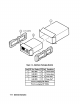
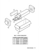
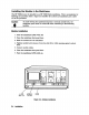
Figure 2-3.
Typical HP 71100A Spectrum
SEC%
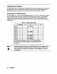
3/8 span cables are used when connecting a second IF Section. Refer to
Figure 2-4.
3/8 span cable.
n
The two
709OOA
LO VIDEO IN,
using the
7/8
span cable.
n
Connect the HP 70903A IF Section VIDEO OUT and the HP
21.4MHz
IN,
using the
70903A
IF Section
21.4-M&
OUT
and the HP
m
Connect the RF section
1
HP 71100A IF Section Cable Connections
I
1
1
1
5061-9021
I7/8
span, 39 cm (15.375 in)
5OSZ
1
Coax SMB (f),
I
1
5061-9017
3/8
span, 19 cm (7.5 in)
1
SOS2
Coax
SMB (f),
1
1
1
5061-9015
in)
span,
9 cm (3.5
l/8
1
5052
1
Coax SMB (f),
L-l!@
HP
Part Number
70903A
RF Cables
single-IF
spectrum analyzer illustration includes cables normally supplied as
accessories when an HP 70903A is ordered separately. Using Table 2-2 for identification and
Figure 2-3 as an example, connect the IF rear-panel cables as described below.
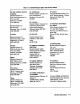
Table 2-2. HP
70903A
in
either an HP 71100A or an HP 71210A spectrum analyzer single-IF ’ and dual-IF section
system, respectively. The cables supplied
with an HP 70903A module that was ordered
separately allow it to be installed as shown in the examples. Longer cables must be ordered
for other configurations. If questions arise concerning other configurations or cabling
arrangements, refer to the installation verification manual for the system master.
Rear-Panel Cables for HP 71100A RF Spectrum Analyzer
Figure 2-3 illustrates typical rear-panel cable connections for an HP 71100A RF Spectmm
Analyzer. This
Connecting the Rear-Panel Cables
This section contains instructions for connecting the rear-panel cables to an HP