About this Manual We’ve added this manual to the Agilent website in an effort to help you support your product. This manual is the best copy we could find; it may be incomplete or contain dated information. If we find a more recent copy in the future, we will add it to the Agilent website. Support for Your Product Agilent no longer sells or supports this product. Our service centers may be able to perform calibration if no repair parts are needed, but no other support from Agilent is available.
Installation and Verification Manual HP 70301A Tracking Generator ABCDE HP Part No. 70301-90039 Printed in USA June 1992 Edition B.0.
Notice The information contained in this document is subject to change without notice. Hewlett-Packard makes no warranty of any kind with regard to this material, including, but not limited to, the implied warranties of merchantability and tness for a particular purpose. Hewlett-Packard shall not be liable for errors contained herein or for incidental or consequential damages in connection with the furnishing, performance, or use of this material. Restricted Rights Legend.
Certification Hewlett-Packard Company certi es that this product met its published speci cations at the time of shipment from the factory. Hewlett-Packard further certi es that its calibration measurements are traceable to the United States National Institute of Standards and Technology, to the extent allowed by the Institute's calibration facility, and to the calibration facilities of other International Standards Organization members.
Safety Symbols The following safety symbols are used throughout this manual. Familiarize yourself with each of the symbols and its meaning before operating this instrument. CAUTION WARNING The CAUTION sign denotes a hazard. It calls attention to a procedure which, if not correctly performed or adhered to, could result in damage to or destruction of the product or the user's work. Do not proceed beyond a CAUTION sign until the indicated conditions are fully understood and met.
General Safety Considerations WARNING The instructions in this document are for use by qualified personnel only. To avoid electrical shock, do not perform any servicing unless you are qualified to do so. The opening of covers or removal of parts is likely to expose dangerous voltages. Disconnect the instrument from all voltage sources while it is being opened. The power cord is connected to internal capacitors that may remain live for five seconds after disconnecting the plug from its power supply.
Contents 1. General Information Introduction . . . . . . . . . . . . . . . . . . Organization . . . . . . . . . . . . . . . . . Chapter 1 Topics . . . . . . . . . . . . . . . Safety . . . . . . . . . . . . . . . . . . . . Description of the HP 70301A Tracking Generator Notation Conventions in this Manual . . . . . . Modules Covered by This Manual . . . . . . . . . Serial Numbers . . . . . . . . . . . . . . . . Manual Updating Supplement . . . . . . . . . Front Panel and Rear Panel Features . . . . . . .
2. Installation Introduction . . . . . . . . . . . . . . . Chapter 2 Topics . . . . . . . . . . . . Module Installation and Removal . . . . . . Installation . . . . . . . . . . . . . . . Removal . . . . . . . . . . . . . . . . Cable Connections Examples . . . . . . . . HP 71210C with HP 70300A and HP 70301A HP-MSIB/HP-IB Addressing . . . . . . . . Modular Measurement System Terminology Functional Terms . . . . . . . . . . . Structural Terms . . . . . . . . . . . Address Matrix . . . . . . . . . . . . .
Figures 1-1. 1-2. 1-3. 1-4. 1-5. 2-1. 2-2. 2-3. 2-4. 2-5. 2-6. Typical Serial Number Label . . . . . . . . . . . . . . . . Front-Panel and Rear-Panel Features . . . . . . . . . . . . Packaging Materials for HP 70001A Mainframe . . . . . . . . Packaging Materials for Modules . . . . . . . . . . . . . . Static-Safe Workstation . . . . . . . . . . . . . . . . . . Module Removal/Replacement . . . . . . . . . . . . . . . Address Map for HP 71400C with HP 70300A and HP 70301A .
1 General Information Introduction This HP 70301A Tracking Generator Installation and Veri cation Manual tells how to install the HP 70301A in an HP 70000 Modular Measurement System. Related information about the system itself can be found in the local oscillator installation and veri cation manual. Organization Chapter 1, \General Information," describes module features and accessories.
Description of the HP 70301A Tracking Generator The HP 70301A microwave tracking generator module is a 3/8-width component of the HP 70000 Modular Measurement System. The HP 70301A operates as a slave to the HP 70900A/B Local Oscillator. When con gured in a spectrum analyzer system, the HP 70301A provides a tracking output from 2.7 GHz to 18 GHz. It can operate in conjunction with an HP 70300A RF tracking generator to provide, from one output port, tracking-output coverage from 10 MHz to 18 GHz.
Figure 1-1. Typical Serial Number Label Manual Updating Supplement A module manufactured after the printing of this manual may have a serial number pre x not listed on the title page, thus indicating a signi cant modi cation to the module. If so, the inclusion of a Manual Updating Supplement means the user should use supplement information to adapt this manual to the modi ed module. If there is no supplement, the manual requires no change.
RF The RF LED indicates that the HP 70301A Tracking Generator RF OUTPUT power is on. That is, the LED is lit when the SRC PWR ON/OFF softkey is ON. UNLEVELED The UNLEVELED LED indicates that the RF OUTPUT power is unleveled during the time the LED is lit. Any of the following can cause unleveled power: Source power (SRC PWR) is set too high. The EXT detector (ALC EXT) is selected with no external detector connected to the front panel EXT ALC INPUT. RF chain malfunctions causing low output power. 10 MHz-2.
300 MHz OUT The signal available at this SMB (m) connector is the 300 MHz IN signal made available for daisy-chaining of the 300 MHz signal to another module such as an RF tracking generator. 21.4 MHz IN The signal applied to this SMB (m) connector comes from either the modules 21.4 MHZ OUT connector or from an external signal generator. 21.4 MHz OUT The signal available at this SMB (m) connector comes from an oscillator internal to the HP 70301A. The signal is normally cabled to the 21.
Figure 1-2.
HP 70900 Local Oscillator Firmware Optimal performance requires compatibility between the HP 70301A Tracking Generator and system master rmware. The HP 70301A will work with HP 70900A LO ROM versions 880901 or later. The following key sequence displays the 70900 rmware version: 4MENU5, Misc , more , service , ROM VERSION . The version date appears in the display's general annotation block.
Accessories Provided with the HP 70301A The HP 70301A Tracking Generator is available separately or as a component in a precon gured system. When ordered separately, the accessories supplied allow the most common system con gurations. Table 1-1 lists accessories being shipped with the HP 70301A at publication of this manual. Contact a Hewlett-Packard Sales and Service O ce for a description of all accessories currently shipped with the HP 70301A.
Returning Instruments for Service Repackaging of a module or the mainframe requires original shipping containers and materials or their equivalents. Hewlett-Packard o ces can provide packaging materials identical to the original (refer to Table 1-4). Figure 1-3 and Figure 1-4 show the packaging materials. When ordering packaging materials to ship a module, it is necessary to order the proper number of foam inserts.
Figure 1-3.
Figure 1-4.
Electrostatic Discharge Information Caution ESD can damage or destroy electronic components. Work at static-safe workstations when servicing assemblies that include electronic components. Figure 1-5 shows an example of a static-safe workstation with two combinations of ESD protection: conductive table mat with wrist strap; conductive oor mat with heel strap. Use these two combinations together. The \Static-Safe Accessories" section provides lists of accessories. Figure 1-5.
Test Equipment Before connecting any coaxial cable to an instrument for the rst time each day, momentarily short together the center and outer conductors of the cable. Before touching the center pin of any connector and before removing any assembly from the instrument, ensure proper use of a grounded, resistor-isolated wrist strap. To prevent buildup of static charge, ensure that all instruments are properly earth-grounded.
Table 1-3. ESD Accessories Available from HP Computer Supplies Description Static control mat, black, hard surface, 1.2 m x 1.5 m (4 ft x 5 ft) Static control mat, brown, soft-surface, 2.4 m x 1.2 m (8 ft x 4 ft) Static control mat, black, hard-surface, 1.2 m x 0.9 m (4 ft x 3 ft) Static control mat, tabletop, 58 cm x 76 cm (23 in. x 3 ft) Antistatic carpet, 1.8m x 1.2m (6 ft x 4 ft) - natural Antistatic carpet, 1.8m x 1.2m (6 ft x 4 ft) - russet Antistatic carpet, 2.4m x 1.
Table 1-4. Hewlett-Packard Sales and Service Offices IN THE UNITED STATES California Hewlett-Packard Co. 1421 South Manhattan Ave. P.O. Box 4230 Fullerton, CA 92631 (714) 999-6700 IN AUSTRALIA Hewlett-Packard Australia Ltd. 31-41 Joseph Street Blackburn, Victoria 3130 895-2895 IN CANADA Hewlett-Packard Co. 301 E. Evelyn Mountain View, CA 94039 (415) 694-2000 Hewlett-Packard (Canada) Ltd.
2 Installation Introduction The HP 70301A Tracking Generator is available separately or con gured in a system. The factory ships precon gured HP 70000 Modular Measurement Systems with all system components addressed and interconnected. This chapter tells about installation of the HP 70301A in an existing system: how to install it, con gure it, and address it. System information in this manual is generalized.
Note If the User Screen softkeys do not appear after power-up, the display window probably is not assigned to a master. To assign it to the master with the lowest column address, press 4DSP5, then SELECT INSTR . To assign the display to the master with the next-highest column address, press the up-arrow key, 485. NNNNNNNNNNNNNNNNNNNNNNNNNNNNNNNNNNNNNN 7. If you connect HP-IB cables after power-on, reset all instruments on the bus by cycling the power.
Cable Connections Examples The gure in this section illustrates the addressing and cable connections for a speci c HP 70000 Modular Measurement System con guration. The section that follows this one, \HP-MSIB/HP-IB Addressing," provides general addressing information. Table 2-1 lists rear-panel cables available for HP 70000 system con gurations. The following pages show recommended cabling for a system that includes the HP 70301A Tracking Generator. Table 2-1.
HP 71210C with HP 70300A and HP 70301A An HP 71210C with HP 70300A and HP 70301A, consists of the following components: HP 70001A Mainframe HP 70900B Local Oscillator HP 70903A IF Section HP 70300A Tracking Generator HP 70310A Precision Frequency Reference HP 70004A Display HP 70902A IF Section HP 70908A RF Section HP 70301A Microwave Tracking Generator Figure 2-2. Address Map for HP 71400C with HP 70300A and HP 70301A The HP 70001A mainframe does not have an HP-MSIB address.
Rear-Panel Cable Connections From Flexible LO I/O Cables To HP 70900B LO OUT HP 70301A LO OUT HP 70908A LO OUT HP 70908A 1st LO IN HP 70300A LO IN HP 70301A LO IN HP 70900B 300 MHZ OUT 1 HP 70900B 300 MHZ OUT 2 HP 70900B HSWP IN/OUT HP 70900B 100 MHZ IN HP 70900B VIDEO IN HP 70900B SWEEP HP 70900B TUNE SPAN * HP 70908A TUNE SPAN * HP 70300A TUNE SPAN HP 70908A 21.4 MHZ OUT HP 70902A VIDEO OUT HP 70902A 21.4 MHZ IN HP 70300A 300 MHZ OUT HP 70301A 21.
Figure 2-3.
HP-MSIB/HP-IB Addressing An element in an HP 70000 Modular Measurement System is a system component able to communicate with other modules over HP-MSIB. Element addresses must adhere to the set of rules de ned in this section (HP-MSIB addressing di ers from HP-IB addressing). For system addressing information, refer to the local oscillator installation and veri cation manual.
Address Matrix The address matrix, as Figure 2-4 shows, is a graphic representation of addresses on the HP-MSIB. The 8-row by 32-column matrix implies 256 available addresses; however, there are actually 255 legal addresses plus an illegal address at row 0, column 31. Figure 2-4. The Address Matrix Each element must have a unique 8-bit binary HP-MSIB address correctly placed on the address matrix.
The master determines its slave-area boundaries by rst searching upward in its own column starting in the master's row, then in each higher column starting in the master's row. The search stops at the boundary column or, if there is no de ning element, after searching column 31. The master uses the following criteria to set slave area boundaries. 1. The left boundary-column equals the master's column address. 2.
3. Set the column switch sections to the binary value of the module's HP-MSIB column number. For example, if the column value is 19, set the switches to binary 10011, as Figure 2-6 shows. Note 2-10 Changing HP-MSIB addresses requires an understanding of HP-MSIB addressing rules. For help with custom con guration addressing, refer to the system-master installation and veri cation manual.
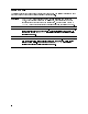
3 Specifications Introduction This chapter contains characteristics and measurement-related speci cations. The system speci cation tables list speci cations and characteristics that are modi ed when the HP 70301A Tracking Generator operates in a HP 71000 MMS Microwave Spectrum Analyzer system. Refer to the system data sheet for any system characteristics or electrical speci cations not found in this chapter. Tables in this chapter list speci cations and characteristics together, in the same format.
System Specifications and Characteristics The tables in this section list characteristics and measurement-related speci cations for HP 71000 MMS Microwave Spectrum Analyzers with an HP 70301A Tracking Generator module. For more information on di erent system con gurations please refer to the HP 71000 MMS Spectrum Analyzer HP 70900 Installation and Veri cation Manual .
Table 3-1. System Specifications and Characteristics Parameters Frequency Range Speci cations 2.7 to 18 GHz with an HP 70301A 10 MHz-18 GHz Frequency Accuracy 6[(Freq. Readout 2 Freq. Ref. Acc.* ) + % of span + 15 Hzy ] % of span is 1% for spans \Span Breakpoint" or 2% for spans > \Span Breakpoint". Span Breakpoint = 10 MHz 2 Nz Frequency Tracking Range 6500 Hz, 1 Hz steps Frequency Tracking Drift <3 Hz/Hour after warm-up Frequency O set Range 65 MHz with external 21.
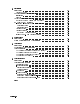
Table 3-1. System Specifications and Characteristics (continued) Parameters Scalar Dynamic Range (20-30 C) Output Attenuator: Range Repeatability Accuracy (referenced to 0 dB attn.) Spectral Purity : (with 02 dBm output power) Speci cations Compute using the following formula: SDR = maximum leveled output power - TG feedthrough 55 dB in 5 dB steps 60.2 dB for any setting Attn. (dB) 5 10 15 20 25 30 35 40 45 50 55 <12.8 GHz (6dB) 0.40 0.60 0.85 0.70 0.95 0.90 1.25 1.80 2.00 2.00 2.20 12.
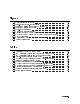
All input/output ports are 50 impedance with <1.5:1 VSWR and with, unless otherwise noted, a maximum safe input/reverse level of +20 dBm ac and 20 V dc. Table 3-2. HP 70301A Input and Output Characteristics, Front Panel Connectors RF OUTPUT EXT ALC INPUT LOW BAND INPUT HP 70301A Characteristics Type N female Max. Safe Reverse Lvl: +20 dBm (0.1 W), 0 V dc Output VSWR, 5 dB attn: 2.7-12.8 GHz <1.5:1 12.8-18 GHz <1.
Table 3-4. General Specifications and Characteristics Parameters Temperature Speci cations Operation Storage 0 C to +50 C 040 C to +75 C EMI (applies to systems only) Conducted and radiated interference is in compliance with CISPR publication 11 (1975) and FTZ 1046. Radiated interference is in compliance with MIL-STD 461B, Part 7, RE02. HP 70301A Weight 6.9 kg (15.2 lb) HP 70301A Dimensions 3/8-width module height 127 mm (5.0 in) width 144 mm (5.7 in) length 467 mm (18.
4 Verification Introduction This chapter describes module operation-veri cation tests that evaluate the electrical performance of an HP 70301A Tracking Generator in a spectrum analyzer system. Run these after repair or adjustment of an HP 70301A assembly. The \Veri cation" chapter in the HP 71000 Modular Spectrum Analyzer Installation and Veri cation Manual for HP 70900B Local-Oscillator-Controlled Modules provides descriptions of operation veri cation tests in the HP 70900 Operation Veri cation software.
Test Descriptions The HP 70900B installation and veri cation manual includes all needed information about equipment requirements and HP 70900 Operation Veri cation software operation. Table 4-1 lists tracking generator tests described in this section and included on the HP 70301A Test Disk 3. Table 4-1 is an extension to a similar table in the HP 70900B installation and veri cation manual. Table 4-1.
TG Absolute Amplitude Accuracy (HP 70301A) TG Absolute Amplitude Accuracy (HP 70301A) Tested Specification AMPLITUDE ACCURACY: Absolute Accuracy Equipment Power Meter MW Power Sensor Equipment Setup With the MW power sensor connected to the power meter, connect the MW power sensor to the RF OUTPUT of the tracking generator. Description This test measures the absolute RF output amplitude accuracy of the tracking generator at its maximum speci ed leveled output power.
TG Vernier Accuracy (HP 70301A) Tested Specification AMPLITUDE ACCURACY: Vernier Accuracy Equipment Power Meter MW Power Sensor Equipment Setup With the MW power sensor connected to the power meter, connect the MW power sensor to the RF OUTPUT of the tracking generator. Description This test measures the incremental RF output amplitude accuracy of the tracking generator over 011 dBm to 0 dBm, the range of the automatic level control (ALC). The tracking generator frequency is set to 2.
TG Frequency Response (HP 70301A) TG Frequency Response (HP 70301A) Tested Specification AMPLITUDE ACCURACY: Amplitude Flatness rel. to 2.7 GHz Equipment Power Meter MW Power Sensor Equipment Setup With the MW power sensor connected to the power meter, connect the MW power sensor to the RF OUTPUT of the tracking generator. Description This test measures the RF output amplitude variations of the tracking generator over its complete frequency range. The tracking generator is set to a frequency of 2.
TG Feedthru (HP 70301A) (using HP 70902A or HP 70903A) Tested Specification Tracking Generator Feedthrough Equipment Power Meter RF Power Sensor 50 Ohm Termination (HP 909D only) Note The type of 50 termination used can greatly a ect the feedthrough level. BNC or Type N terminations have too much leakage, and should not be used. The leakage of the HP 909D termination is low enough not to a ect the measurement.
TG Feedthru (HP 70301A) 4. The tracking generator frequency is set to the frequency of the peak response, and a power meter is used to set the output amplitude to 010 dBm 60.05 dB. 5. The spectrum analyzer settings are changed as follows: Span is set to 0 Hz. Video bandwidth is set to 3 Hz. Sweep time is set to a value which assures that the trace data elements are uncorrelated. 6. A sweep is taken. The tracking generator feedthrough level is equal to the average of the trace elements.
5 Troubleshooting Introduction Review Chapter 2 of this manual to ensure that the module addressing switches are properly set, cabling is correct, and that the module is securely seated in the mainframe. This module-level troubleshooting chapter provides information on the front-panel status lights, indicator lights, and those error messages produced by the HP 70301A Tracking Generator module. (For component-level troubleshooting information, refer to the HP 70301A service manuals.
2. Status Indicators The mainframe and all elements have two types of status indicators. The ERR (error) indicator indicates a fault of some kind. The ACT (active) indicator shows that an element is active (that it is being controlled or accessed). The status indicators for a display are the letters E and A in the lower right corner of the display in the display status block. All other elements have ERR and ACT indicators on the front panel.
3. Programs The following software and rmware aids help evaluate : a. Power-On Self-Test. b. System Diagnostics. c. Module Veri cation. d. System Performance Programs. e. System Analyzer Operation Veri cation. a. Power-On Self-Test: Switching line power on causes execution of a module self-test of each module in an HP 70000 Modular Measurement System. The test veri es the ability of the module to communicate with the system controller on the system bus (HP-MSIB).
manual for a list of error messages produced by the HP 70301A Tracking Generator module. For error messages generated by other modules, refer to the system-master installation and veri cation manual. Refer to the troubleshooting chapter in the system-master installation and veri cation manual for more details about test results. Note CAUTION The HP 70000XL con guration precludes the use of other DLPs because most of the available memory is used for the HP 70000XL Personality software.
4. Error Messages CAUTIONS The HP 70301A Tracking Generator module contains components and assemblies that electrostatic discharge (ESD) can damage. Service the module only at a static-safe work station. Refer to Chapter 1 for lists of precautions and static-safe accessories and for a work-station description. The HP 70301A Tracking Generator module contains both metric and inch hardware. Refer to Chapter 7 for identi cation of hardware type.
Operating Errors (2000-2999) Operating errors result from incorrect use of the analyzer, usually during remote operation. The operation and programming manuals explain manual and remote analyzer operation. 2001 Illegal cmd (Illegal command) | User-generated system protocol error. This error occurs when the module encounters a command it does not recognize. This can be caused by the master element's sending such a command, a problem internal to the module, or an open cable between the master and module.
7005 7009 7078 7079 A8W4 Coax cable 321.4 MHz error | The 321.4 MHz signal is not correct at A6J1, the output of the 321.4 MHz ampli er (A6U1) on the 321.4 MHz Reference Board Assembly. Verify that the correct cables are connected at the rear-panel 300 MHz IN and 21.4 MHz IN connectors. If the internal oscillator is selected, there must be a cable connecting the 21.4 MHz OUT and 21.4 MHz IN rear-panel connectors. Instrument preset defaults to the internal oscillator.
Index A accessories, 1-8 shipped with module, 1-8 address, binary, 2-8 addressing examples, 2-3 address map cursor, 5-2 address matrix, 2-8 address switches, 2-9 column address, 2-9 row address, 2-9 C cable connections, 2-3 connector torque, 2-3 conventions notation, 1-2 softkey, 1-2 D de ning element, 2-9 description HP 70301A Tracking Generator, 1-2 initial inspection, 1-8 installing the HP 70301A, 2-1 M manual coverage, 1-2 errors in the manual, 1-2 modi ed modules, 1-2 serial numbers, 1-2 updating,
general, 3-6 HP 71201A, 3-2 veri cation of, 4-1 Status Indicator ACT, 5-3 ERR, 5-3 status indicators, 5-2 ACT, 5-2 active, 5-2 ERR, 5-2 System diagnostics, 5-3 T terminology address matrix, 2-7 address protocol, 2-7 address switches, 2-7 characteristics, 3-1 element, 2-7 independent, 2-7 instrument, 2-7 mainframe, 2-7 Index-2 master, 2-7 module, 2-7 slave, 2-7 speci cations, 3-1 stand-alone instrument, 2-7 sub-master, 2-7 Test Calibration, 5-4 Module performance, 5-4 Operation Veri cation, 5-4 Self-Test,