Service Guide HP 70909A/70910A RF Section ABCDE HP Part No. 70909-90035 Printed in USA June 1998 Edition A.0.
Notice The information contained in this document is subject to change without notice. Hewlett-Packard makes no warranty of any kind with regard to this material, including, but not limited to, the implied warranties of merchantability and tness for a particular purpose. Hewlett-Packard shall not be liable for errors contained herein or for incidental or consequential damages in connection with the furnishing, performance, or use of this material. Restricted Rights Legend.
Certi cation Hewlett-Packard Company certi es that this product met its published speci cations at the time of shipment from the factory. Hewlett-Packard further certi es that its calibration measurements are traceable to the United States National Institute of Standards and Technology, to the extent allowed by the Institute's calibration facility, and to the calibration facilities of other International Standards Organization members.
Safety Symbols The following safety symbols are used throughout this manual. Familiarize yourself with each of the symbols and its meaning before operating this instrument. CAUTION The CAUTION sign denotes a hazard. It calls attention to a procedure which, if not correctly performed or adhered to, could result in damage to or destruction of the product or the user's work. Do not proceed beyond a CAUTION sign until the indicated conditions are fully understood and met.
General Safety Considerations WARNING The instructions in this document are for use by quali ed personnel only. To avoid electrical shock, do not perform any servicing unless you are quali ed to do so. The opening of covers or removal of parts is likely to expose dangerous voltages. Disconnect the instrument from all voltage sources while it is being opened. The power cord is connected to internal capacitors that may remain live for ve seconds after disconnecting the plug from its power supply.
Contents 1. Getting Started Overview of Servicing . . . . . . . . . . . . . . . . . . . . . . . . . . . . Contacting Hewlett-Packard for Servicing or Ordering Parts . . . . . . . . . . 2. Installing and Con guring Module Veri cation Software Computer Software Requirements . . . . . . Computer Hardware Requirements . . . . . . Installing Software and Creating Working Copies Con guring Module Veri cation Software . . . Working with the TSCRIPT File . . . . . . . . Working with the MS_TABLE Data File . . . .
Adjustment 06. YTF Alignment . . . . . . . . . . . . . . . . . . . . . . . . 6. Veri cation Tests Before You Begin Testing . . . . . . . . . . . . . . . . . Overall Test Setup . . . . . . . . . . . . . . . . . . . . Test 01. Switch Repeatability - HP 70910A Only . . . . . . Test 02. External Mixer Gain Calibration . . . . . . . . . Test 03. Gain and Flatness Calibration . . . . . . . . . . Test 04. Flatness Below 50 MHz . . . . . . . . . . . . . Test 05. Microwave Gain and Noise Figure . . . . . . . .
8. Replacing Major Assemblies Module Cover . . . . . . . . . . . . . . . . . . . . . . Front Panel . . . . . . . . . . . . . . . . . . . . . . . Rear Panel . . . . . . . . . . . . . . . . . . . . . . . A2 RF First Converter . . . . . . . . . . . . . . . . . . A5, A7, A8, A9 Second Converter . . . . . . . . . . . . A6 Programmable Gain Ampli er . . . . . . . . . . . . . A10 Last Converter . . . . . . . . . . . . . . . . . . . A11 5 dB Step Attenuator . . . . . . . . . . . . . . . .
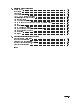
Figures 1-1. 3-1. 4-1. 4-2. 4-3. 4-4. 5-1. 5-2. 5-3. 5-4. 5-5. 5-6. 5-7. 5-8. 5-9. 5-10. 5-11. 5-12. 5-13. 5-14. 5-15. 5-16. 5-17. 5-18. 5-19. 5-20. 5-21. 5-22. 5-23. 5-24. 5-25. 5-26. 5-27. 5-28. 5-29. 5-30. 5-31. 5-32. 5-33. 5-34. 5-35. 5-36. 5-37. 5-38. Typical Serial Number Label . . . . . . . . . . . . . . . . . . . . . . . . Typical Serial Number Label . . . . . . . . . . . . . . . . . . . . . . . . Spectrum Analyzer Calibration Setup . . . . . . . . . . . . . . . . . . . .
5-39. 5-40. 6-1. 6-2. 6-3. 6-4. 6-5. 6-6. 6-7. 6-8. 6-9. 6-10. 6-11. 6-12. 6-13. 6-14. 6-15. 6-16. 6-17. 6-18. 6-19. 6-20. 6-21. 6-22. 6-23. 6-24. 7-1. 7-2. 7-3. 7-4. 7-5. 7-6. 8-1. 8-2. 8-3. 8-4. 8-5. 8-6. 8-7. 8-8. 8-9. 8-10. 8-11. 8-12. 8-13. 8-14. 8-15. 8-16. 9-1. 9-2. 9-3. 9-4. 9-5. 9-6. 9-7. Equipment Setup for Adjustment 06. YTF Alignment . . . . . . . . . A19 OFFSET (R38) and GAIN (R39) Adjustments . . . . . . . . . . . . Veri cation Tests Equipment Matrix . . . . . . . . . . . . . . . . . .
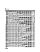
9-8. 9-9. 9-10. 9-11. Overall Parts Identi Overall Parts Identi Overall Parts Identi Overall Parts Identi Contents-6 cation Drawing, Right Side View, Exploded (3 of 4) cation Drawing, Right Side View, Exploded (4 of 4) cation Drawing, Left Side View, Exploded . . . . cation Drawing, Rear View . . . . . . . . . . . . . . . . . . . . . . . . . . .
Tables 1-1. 1-2. 7-1. 7-2. 7-3. 9-1. 9-2. 9-3. 9-4. 9-5. 9-6. HP Service Centers . . . . . . . . . . . . . . . . . . . . . . . Packaging for a 2/8 Module (RF Section) . . . . . . . . . . . . . . Static-Safe ESD Accessories . . . . . . . . . . . . . . . . . . . Default HP-MSIB Address Map . . . . . . . . . . . . . . . . . . A11 5 dB Step Attenuator Logic . . . . . . . . . . . . . . . . . Cables for the HP 70909A RF Section and HP 70910A RF Section . .
1 Getting Started Overview In this chapter you will learn about: Various types of test software available for your RF section The organization of this service guide and component-level repair information How to contact Hewlett-Packard for servicing or ordering parts This chapter introduces you to servicing and the various types of test software available for your RF section.
Overview of Servicing 1-2 Getting Started
Overview of Servicing This service guide is part of an Option OB3 package which includes test software and two manuals. Test Software Manual 1 Manual 2 Module Veri cation Software HP 70909A/70910A Service Guide HP 70909A/70910A Component Level Information Package Types of Test Software Available There are three categories of test software available, and this service guide documents the use of module veri cation tests.
Overview of Servicing how to run the module veri cation software tests, and nally, you'll learn how to create, edit, print, or purge a CAL FACTOR data le using the Calibration Editor program. Chapter 4 \Test Equipment and Calibrations" This chapter contains the test equipment setups for all calibration procedures that must be performed in order to optimize module performance when assemblies are changed, repaired, or adjusted.
Overview of Servicing Information Not Covered in Manual 1 or 2 System con gurations are documented in the HP 70000 Modular Spectrum Analyzer Installation and Veri cation Manual and HP 71910P Wide-Bandwidth Receiver User's Guide. Error codes not covered in the troubleshooting chapter of this manual (Chapter 7) may be found in the HP 70000 Modular Spectrum Analyzer Installation and Veri cation Manual, HP 71910P Wide-Bandwidth Receiver User's Guide, and additional module speci c service guides.
Contacting Hewlett-Packard for Servicing or Ordering Parts Contact Hewlett-Packard for service or ordering parts. Service Before calling Hewlett-Packard or returning your RF section for service, please read your warranty information. Warranty information is printed at the front of this service guide. Ordering Parts To order parts, contact the HP Service Center closest to you. In any correspondence or telephone conversations, refer to the RF section by its full model number and full serial number.
Contacting Hewlett-Packard for Servicing or Ordering Parts A current list of Hewlett-Packard Service Centers can be accessed on the Internet at: http://www.tmo.hp.com/tmo/contacts/ If you do not have access to the Internet, one of the following Hewlett-Packard locations can direct you to your nearest Hewlett-Packard representative: Table 1-1.
Contacting Hewlett-Packard for Servicing or Ordering Parts Returning Your RF Section for Service Hewlett-Packard has sales and service o ces around the world to provide complete support for your RF section. To obtain servicing information or to order replacement parts, contact the nearest Hewlett-Packard sales and service o ce listed in Table 1-1. Use the following procedure to return your RF section to Hewlett-Packard for service: 1.
Contacting Hewlett-Packard for Servicing or Ordering Parts Table 1-2.
Installing and Con guring Module Veri cation Software Overview 2 In this chapter you will learn about: Computer software and hardware requirements Keyboard compatibility Installing module veri cation software, TSCRIPT, and MS TABLE Purging module veri cation software, TSCRIPT, and MS TABLE Test equipment requirements including default models and HP-IB addresses Editing the TSCRIPT le Specifying storage locations for CAL FACTOR data les and test result data This chapter prepares you to install and con gur
Computer Software Requirements To run the module veri cation software, your computer system must have the following components: HP BASIC 6.3 or above and the appropriate binary les loaded in the computer. If necessary, refer to an HP BASIC reference manual. CLOCK CRTA CRTB CRTX CS80 DCOMM3 DISC EDIT ERR GRAPH GRAPHX HFS2 HPIB IO KBD MAT MS PDEV1 SRM3 XREF1 Optional: Required only for DEBUG. 2 Optional: Required only for HFS (hierarchical le system) environment.
Computer Hardware Requirements Computer Hardware Requirements To run the module veri cation software, your computer system must have the following: Computer HP 9000 Series 300 controller HP BASIC HP BASIC 6.3 or above and the appropriate binary les loaded RAM 8 MB of RAM Interface One HP-IB interface Hard Disk SRM or HFS hard disk with 5 MB available space Floppy Disk Dual or single 3.
Computer Hardware Requirements Using an HP 98203C Keyboard with a Series 300 Computer If you use an HP 98203C (Nimitz) keyboard, the equivalent keys are: HP 46021A Keyboard HP 98203C Keyboard 4 5 (home) 4Delete 4Enter5 line5 4DEL LN5 4Return5 4Enter5 4Select5 4Enter5 4Stop5 4Menu5 or 4Continue5 4Pause5 NNNNNNNNNNNNNNNNNNNNNNNNNN Continue 4Continue5 To highlight an item in the menu, use 485 and 495, or turn the keyboard knob. To choose the highlighted item, press 4ENTER5.
Installing Software and Creating Working Copies Installing Software and Creating Working Copies Overview In this section you will perform the following steps: Run INSTALL, from a oppy disk drive or other logical device, and create a working copy. The INSTALL program performs the following: a. Assigns a source disk drive (and optional directory) b. Assigns a destination disk drive (and optional directory) c.
Installing Software and Creating Working Copies To create a working copy on an SRM or HFS hard disk In this section, you will learn how to create a working copy of module veri cation software on either an SRM (shared resource manager) or HFS (hierarchical le structure) hard disk drive. The following steps assume that you have either an SRM or HFS hard disk system and a 3.5 inch double-sided oppy disk drive. 1. Insert Executive Disk 1 of the module veri cation software into a 3.
Installing Software and Creating Working Copies 4. Read the installation overview screen that appears and press any key to continue. d INSTALLATION OVERVIEW ===================== a HP 70909A/70910A Module Verification Software must be installed on an SRM or HFS hard disk. This installation creates a working copy. After installation, store the original disks in a safe place; they will only be needed in the event that the working copy becomes corrupt or damaged.
Installing Software and Creating Working Copies 6. At the program prompt, enter the MSVS, with an optional-directory path, of where the module veri cation software is to be installed and press 4Return5; this sets the destination HFS/SRM directory path. Press 4Return5 to accept /OPV9000/70909A_10A/ as the default destination HFS/SRM directory path. If you want the module veri cation software installed in a di erent directory, substitute a di erent destination HFS/SRM directory path and press 4Return5.
Installing Software and Creating Working Copies NNNNNNNNNNNNNNNNNNNNNNNNNN 7. When prompted, remove Executive Disk 1, insert Executive Disk 2, and press Continue . NNNNNNNNNNNNNNNNNNNNNNNNNN If you have an HP 46021A keyboard, and the Continue softkey does not appear on the display, press 4Menu5. If you are using an HP 98203C keyboard, refer to the section \Using an HP 98203C Keyboard with a Series 300 Computer". 8. When prompted, remove Executive Disk 2, insert the Tests Disk, and press Continue .
Installing Software and Creating Working Copies To purge a copy of module veri cation software CAUTION If the directory being purged contains les that you wish to retain, move (relocate) the les to a di erent directory before performing this procedure. Note In order to purge both les and a directory, your current MSI can not be set to the directory that you are purging. If you are using HP BASIC 6.3 through HP BASIC 6.4: 1. Type, WILDCARDS UX; ESCAPE "\" 2.
Con guring Module Veri cation Software Con guring Module Veri cation Software Before running module veri cation software, it should be con gured to work with the test equipment and le system that you are using. Overview How to proceed: 1. Con gure the test equipment settings by editing the TSCRIPT le. When editing the TSCRIPT le, refer to the \Test Equipment Requirements". 2. Run the EDIT_MSTAB program and specify the storage locations of CAL FACTOR data les and test results.
Con guring Module Veri cation Software Test Equipment Requirements The HP 70909A/70910A module veri cation software only contains drivers for the equipment shown in the table below. The equipment is listed in order of preferred model number. In all cases, the speci ed aging rate requirement is 1009 ms/day. The microwave source, synthesized source, and calibrated spectrum analyzer listed in the following table have internal time bases that meet the aging rate requirement.
Con guring Module Veri cation Software Equipment TSCRIPT Label Default HP-IB Address SYN4 718 Noise source Noise gure meter NSRC NMTR1 NONE 708 Power meter PM11 , 2 MWPS LPPS 713 713,0,0 712 713,0,1 NONE NONE LFPS NONE DVM 722 HP 70000 Components Local oscillator source Display Mainframe IF section Module Extender Frequency reference Meters PM21 Power sensor Precision DVM ,2 Recommended Model HP 70900B local oscillator source (upgraded with rmware version 911021 [V.U.F. B.04.
Con guring Module Veri cation Software Ampli ers HP 83006A microwave ampli er HP 8447A RF ampli er, or HP 8447D RF ampli er, or HP 8447E RF ampli er, or HP 8447F RF ampli er Standard Equipment HP 8493C Option 006 coaxial xed attenuator HP 8493C Option 010 coaxial xed attenuator HP 11667B power splitter HP 909D Option 011 50 3.
Con guring Module Veri cation Software Connecting Test Equipment HP-IB Interface Cables 1. Connect the HP-IB interface to the computer port. If the computer has an HP 98624A HP-IB interface: a. Connect the HP-IB interface to the port labeled HP-IB SELECT CODE 8. b. Check that the address switch on the HP 98624A HP-IB interface matches the HP-IB controller device address. c. If necessary, refer to HP 9000 Series 200/300 Peripheral Installation Guide, Volume I.
Working with the TSCRIPT File Overview In this procedure, you will perform the following steps: a. Create a backup copy of the TSCRIPT le before making changes. b. Load and edit the TSCRIPT le so that it matches your test equipment model numbers and HP-IB addresses. c. Save the edited version of the TSCRIPT le. d. Run the C_TSCRIPT program which creates a new TESTINFO BDAT le.
Working with the TSCRIPT File To create a backup copy of the TSCRIPT le Using HP BASIC, create a copy of the TSCRIPT le. For example: 1. Set the MSI to the MSVS of the disk drive that contains your working copy of module veri cation software. (For example, MSI "/OPV9000/70909A_10A:,1400,0" or MSI "/OPV9000/70909A_10A:HFS".) 2. Type, COPY "TSCRIPT" TO "TSCRIPT_BK" If ERROR 54 Duplicate file name is displayed, the TSCRIPT le has been previously backed up.
Working with the TSCRIPT File To edit test equipment and HP-IB address lists in the TSCRIPT le If your test equipment model numbers and HP-IB addresses are di erent from the default test equipment list that is displayed, you can edit the TSCRIPT le so that it matches your test equipment. Note Edit only the following sections, and only in the method described.
Working with the TSCRIPT File Note If you are using an HP 8360 Series synthesized sweeper for SYN1 or SYN2, it must be set to HP 8340 Compatibility Mode. Press the following keys on the HP 8360 Series synthesized sweeper: a. Press 4LOCAL5. b. Press 4MENU5 from the SYSTEM group. c. Press HP-IB MENU . d. Press Analyzr from the ..Programming Language... group so that an asterist (*) appears next to the word Analyzr.
Working with the TSCRIPT File 7. Using the 485 key, scroll to the DEFAULT_ADDRESSES(. This section of the TSCRIPT le de nes a list of default test equipment addresses; this list is used by module veri cation software. Valid addresses are 02 to 20, and 22 to 30; address 21 is reserved for the controlling computer. Valid select codes are computer speci c; normally, they are 7 or 8 (the default is 7); a label near the HP-IB port on your computer should identify the bus address.
Working with the TSCRIPT File To specify the default ADDRESS TYPE and ADDRESS for the UUT If your RF section is set to an HP-IB and MSIB address other than the factory preset address of 718, 6, 18, you may modify the TSCRIPT le so that it uses the actual address of your RF section: 1. Scroll to the DEFAULT_ADDRESSES( section of the le and edit the ADDRESS for the UUT. 2. Enter the HP-IB address (ADDRESS) followed by the MSIB row and column address; each entry must be separated by a comma.
Working with the TSCRIPT File To save the edited TSCRIPT le 1. Press 4Stop5 to exit editing mode. 2. Type RE-SAVE "TSCRIPT" . 3. Press 4Return5. Wait for the asterisk (*) in the lower right-hand corner of the display to disappear. 4. Type LOAD "C_TSCRIPT",1 and press 4Return5. This creates a new TESTINFO BDAT le. When Done. appears on the computer display, proceed to \Working with the MS_TABLE Data File".
Working with the MS_TABLE Data File Working with the MS_TABLE Data File A separate program referred to as the Mass Storage Table Editor (EDIT_MSTAB) is used to specify the storage locations of CAL FACTOR data les and test results. The EDIT_MSTAB program modi es entries in the MS_TABLE data le. To change the storage locations of CAL FACTOR data les or test results 1.
Working with the MS_TABLE Data File 2. Read the present path and lename being displayed and verify that they are correct. d MSTABLE EDITOR v1.0 =================== a The present path and filename for the location of the file MS_TABLE is:> c Do you want to change the path and/or filename for the location of MS_TABLE? (y/n) b Enter n and press 4Return5 if the directory path and lename being displayed are correct.
3 Running Module Veri cation Software Overview In this chapter you will learn about: Loading module veri cation software from an SRM or HFS hard disk Entering information about your RF section (UUT) Directing test reports to the printer or the display Running adjustments and veri cation tests Working with the Calibration Editor and CAL FACTOR data les This chapter prepares you to run the module veri cation tests on your RF section. You will learn how to load module veri cation software.
Loading from an SRM or HFS Hard Disk 1. Assign the MSI (mass storage is:) to the hard disk drive and directory path of where the module veri cation software is installed; this is the MSVS along with the optional-directory that was speci ed in the procedure, \To create a working copy on an SRM or HFS hard disk" in Chapter 2. (For example, MSI "/OPV9000/70909A_10A:,1400,0" or MSI "/OPV9000/70909A_10A:HFS".) 2. Type LOAD "OPV",1 and press 4Return5. 3. Highlight the model number being tested and press 4Return5.
Entering Information About Your RF Section (UUT) Entering Information About Your RF Section (UUT) If you are using OPV module veri cation software, use the instructions in this section to enter information that is required before accessing the Main Test Menu.
Entering Information About Your RF Section (UUT) To change the UUT's default HP-IB and MSIB address d c a =============== UUT: HP 70909A =============== SERIAL NUMBER 0000A00000 FFFFFFFFFFFFFFFFFFFFFFFFFFFFFFF ADDRESS TYPE OTHER ADDRESS 718,6,18 CONTROLLER OPTIONS TEMPERATURE 23.0 DEG C HUMIDITY 50.0 % LINE FREQUENCY 60 Hz b If your RF section is set to an HP-IB and HP-MSIB address other than the factory preset address of 718, 6, 18, you can modify the HP-IB and MSIB address for the UUT. 1.
Entering Information About Your RF Section (UUT) To change the UUT's temperature setting d c ========== UUT: HP 70909A =============== SERIAL NUMBER 0000A00000 ADDRESS TYPE OTHER ADDRESS 718,6,18 CONTROLLER OPTIONS FFFFFFFFFFFFFFFFFFFFFFFFFFFFFFFFFFFFFFF TEMPERATURE 23.0 DEG C HUMIDITY 50.0 % LINE FREQUENCY 60 Hz a b You can enter the ambient temperature of the area in which the RF section is operating. This temperature data becomes part of the test record. 1.
Entering Information About Your RF Section (UUT) To change the UUT's line frequency d c =============== UUT: HP 70909A =============== SERIAL NUMBER 0000A00000 ADDRESS TYPE OTHER ADDRESS 718,6,18 CONTROLLER OPTIONS TEMPERATURE 23.0 DEG C HUMIDITY 50.0 % FFFFFFFFFFFFFFFFFFFFFFFFFFFFFFFFFFFFFFF LINE FREQUENCY 60 Hz FFFFFFFFFFFFFF 60 Hz 50 Hz 400 Hz a b You can enter the power line frequency the RF section is using. This line frequency data is recorded with the test record. 1.
Entering Information About Your RF Section (UUT) To resolve equipment models and HP-IB addresses When the module veri cation software begins, it started with a default list of test equipment and their associated HP-IB addresses. If the model numbers and addresses shown on your display match the model numbers and addresses of your test equipment, you can continue to the next section.
Entering Information About Your RF Section (UUT) To print the default equipment list If you have an HP-IB printer connected to your computer, you can print the default test equipment list when you are in the test equipment menu screen. The HP-IB printer must be set to address 01 and can only be used with select code 7. This means that, an HP-IB printer can only be used when it is set to HP-IB address 701; module veri cation software will not recognize an HP-IB printer at any other address. 1.
Entering Information About Your RF Section (UUT) To resolve address con icts The program checks for equipment address con icts and reports any con icts that are found. d c There is a device address conflict among the instruments that are used for testing. Two or more instruments are assigned at address EDIT ADDR. --> 727 <-ABORT a b 1. To return to the equipment screen and edit the address, select EDIT ADDR.
Running from the Main Test Menu Module veri cation tests are used to test modules so that when assembled into a system, the system meets the system's speci cations. All of the adjustments and veri cation tests are automated and computer controlled. d ==================== TEST LIST ==================== a ???????????????????????????????????????????????????????? c Test Equipment Calibration Menu Adj. 01. Power Supply Voltage Checks Adj. 02. 1st LO Power Adj. 03. 2nd Converter Adjustments Menu Adj. 04.
Running from the Main Test Menu To abort from the main test menu 1. Press 4 5 to abort from the main test menu. A dialog box asks if you wish to return to the MMS module selection menu. d c Return to main MMS module selection menu? YES FFFFFFF NO a b Select YES to return to the main MMS module selection menu. Select NO to view the test list.
Working with the Calibration Editor Both the OPV and the CTM module veri cation software use the Calibration Editor described in this section. The Calibration Editor provides the ability to create, select, edit, print, or purge a CAL FACTOR data le, or change the directory path (MSVS) of where CAL FACTOR data les are located in your le system. If a power sensor is used during an equipment calibration, adjustment, or veri cation test, a CAL FACTOR data le is required.
Working with the Calibration Editor Starting the Calibration Editor There are two ways to start the Calibration Editor: Manually The Calibration Editor can be started manually through the Utilities Menu. Automatically If module veri cation software tries to access a CAL FACTOR data le for a power sensor and one can not be found or a power sensor has passed its calibration due date, a warning screen similar to the following is displayed.
Working with the Calibration Editor 1. If the Calibration Editor starts automatically, because the required CAL FACTOR data le cannot be found, the following screen is displayed. The Calibration Editor can be used to find the CAL FACTOR data file that was expected or a new CAL FACTOR data file can be created. ...CAL FACTOR data file that is expected: CF8xxxxxxx The following data is required if you decide to create a new CAL FACTOR data file. c ...
Working with the Calibration Editor 4. After verifying or updating the computer's internal clock, the following screen is displayed. d c ==========Enter the CAL FACTOR volume MSVS========== /OPV9000/70909A_10A/CALFACTORS a b Press 4Return5 if the directory path (MSVS) being displayed is the correct location of the power sensor CAL FACTOR data les in your le system. This directory path (MSVS) is saved in the MS_TABLE data le.
Working with the Calibration Editor 5. After verifying or updating the CAL FACTOR volume (MSVS), the following screen is displayed.
Working with the Calibration Editor EXIT d Use this selection to exit the Calibration Editor. Before exiting, the following screen is displayed: Do you want to exit the Calibration Editor (YES/NO)? a Select ABORT to exit the Calibration Editor, abort the current test, and return to the main test menu. ??????? YES NO ABORT c YES NO ABORT Use this selection to exit the Calibration Editor and continue the test. Use this selection to continue using the Calibration Editor and redisplay its menu.
Working with the Calibration Editor Creating a new CAL FACTOR data le If a CAL FACTOR data le does not exist for the power sensor that is being used, one must be created. During this procedure, you will select a power sensor model from a list, then you will enter its serial number and calibration due date. This information is necessary before proceeding to the POWER SENSOR EDITING menu. 1.
Working with the Calibration Editor POWER SENSOR SERIAL POWER SENSOR CAL DUE Naming conventions for CAL FACTOR data les: Each CAL FACTOR data le has a unique le name, made up of three parts, that are derived from the values supplied to the POWER SENSOR INFORMATION menu. Part 1 Each CAL FACTOR data le name begins with the two letters CF.
Working with the Calibration Editor If you enter the current date or a date earlier than the current date as the POWER SENSOR CAL DUE entry, module veri cation software will view the power sensor as overdue for calibration. This will start the Calibration Editor program and display a warning screen similar to the following: The Calibration Editor has been started because the power sensor designated on the Power Sensor Identification menu has past its calibration due date. ...
Working with the Calibration Editor If you fail to load the CAL FACTOR data le that is required for the power sensor that was designated on the Power Sensor Identification menu, a warning screen similar to the following is displayed: The Calibration Editor has been re-started because the CAL FACTOR data file required for the power sensor designated on the Power Sensor Identification menu does not match. ...CAL FACTOR data file that was expected: ...
Working with the Calibration Editor Selecting a CAL FACTOR data le This menu selection is only available when the Calibration Editor program is started automatically. If a CAL FACTOR data le does not exist for the power sensor that is being used in your test system, one must be created. (Refer to \Creating a new CAL FACTOR data le".
Working with the Calibration Editor If you fail to load the CAL FACTOR data le that is required for the power sensor that was designated on the Power Sensor Identification menu, a warning screen similar to the following is displayed: The Calibration Editor has been re-started because the CAL FACTOR data file required for the power sensor designated on the Power Sensor Identification menu does not match. ...CAL FACTOR data file that was expected: ...
Working with the Calibration Editor Editing a CAL FACTOR data le During this procedure, you can either continue the steps that you started when \Creating a new CAL FACTOR data le", or you can access an existing CAL FACTOR data le and edit its entries. Choose one of the following three options: If you are continuing from the procedure, \Creating a new CAL FACTOR data le", proceed to the procedure \Using the POWER SENSOR EDITING menu".
Working with the Calibration Editor d Choosing this selection displays a list of frequencies and their associated calibration factors that are presently stored in the CAL FACTOR data le being edited. 1.000 2.000 4.000 6.000 8.000 10.000 12.000 14.000 16.000 18.000 c EDIT FREQUENCY LIST d GHz GHz GHz GHz GHz GHz GHz GHz GHz GHz 100.00 99.00 100.00 100.00 100.00 100.00 100.00 96.00 100.00 100.00 % % % % % % % % % % 1. Use 485 or 495 to highlight a frequency. 2.
Working with the Calibration Editor d 3. Use 485 or 495 to highlight your choice and press 4Return5. To select the various elds, use the 465 or 475 arrow keys to move the cursor. To change a value, use the 485 or 495 arrow keys. Press 4Return5 when you are nished editing the values. 4. Press 4 5 to proceed to the next screen. A new dialog box asks if you wish to edit the calibration factors associated with any entries that you have made.
Working with the Calibration Editor If you enter the current date or a date earlier than the current date as the POWER SENSOR CAL DUE entry, module veri cation software will view the power sensor as overdue for calibration. This will start the Calibration Editor program and display a warning screen similar to the following: The Calibration Editor has been started because the power sensor designated on the Power Sensor Identification menu has past its calibration due date. ...
Working with the Calibration Editor If you fail to load the CAL FACTOR data le that is required for the power sensor that was designated on the Power Sensor Identification menu, a warning screen similar to the following is displayed: The Calibration Editor has been re-started because the CAL FACTOR data file required for the power sensor designated on the Power Sensor Identification menu does not match. ...CAL FACTOR data file that was expected: ...
Working with the Calibration Editor Printing a CAL FACTOR data le If a CAL FACTOR data le does not exist for the power sensor that is being used, one must be created. (Refer to \Creating a new CAL FACTOR data le".) If a CAL FACTOR data le does exist for the power sensor that is being used, use the 485 and 495 arrow keys to select PRINT CAL FACTOR FILE from the POWER SENSOR CAL FACTOR MANAGEMENT menu and press 4Return5.
Working with the Calibration Editor NNNNNNNNNNNNNNNNNNNNNNNNNNNNNNNNNNNNNNNNN PRINT SPOOLER d Choosing PRINT SPOOLER displays a screen that requests the MSVS or directory path of the print spooler. c Enter the SRM or UNIX print spooler path. (For example, LP:REMOTE or | lp.
Working with the Calibration Editor Changing the CAL FACTOR data le volume (MSVS) 1. Using the 485 and 495 arrow keys, select CHANGE CAL FACTOR VOL from the POWER SENSOR CAL FACTOR MANAGEMENT menu and press 4Return5.
4 Test Equipment and Calibrations Overview In this chapter you will learn about: Test equipment requirements and their setup con gurations Test equipment calibrations as well as when and how often calibrations are required External frequency reference requirements This chapter contains the test equipment setups for all calibration procedures that must be performed in order to optimize module performance when assemblies are changed, repaired, or adjusted.
Test Equipment Requirements The HP 70909A/70910A module veri cation software only contains drivers for the equipment shown in the table below. The equipment is listed in order of preferred model number. In all cases, the speci ed aging rate requirement is 1009 ms/day. The microwave source, synthesized source, and calibrated spectrum analyzer listed in the following table have internal time bases that meet the aging rate requirement.
Test Equipment Requirements Equipment TSCRIPT Label Default HP-IB Address SYN4 718 Noise source Noise gure meter NSRC NMTR1 NONE 708 Power meter PM11 , 2 MWPS LPPS 713 713,0,0 712 713,0,1 NONE NONE LFPS NONE DVM 722 HP 70000 Components Local oscillator source Display Mainframe IF section Module Extender Frequency reference Meters PM21 Power sensor Precision DVM 1 2 ,2 Recommended Model HP 70900B local oscillator source (upgraded with rmware version 911021 [V.U.F. B.04.
Test Equipment Requirements Ampli ers HP 83006A microwave ampli er HP 8447A RF ampli er, or HP 8447D RF ampli er, or HP 8447E RF ampli er, or HP 8447F RF ampli er Standard Equipment HP 8493C Option 006 coaxial xed attenuator HP 8493C Option 010 coaxial xed attenuator HP 11667B power splitter HP 909D Option 011 50 3.
Test Equipment Calibrations Test Equipment Calibrations The module veri cation tests require spectrum analyzer instrument calibration and scalar network analyzer atness calibration. These calibrations store calibration data for veri cation tests measurement-correction in controller common memory.
Spectrum Analyzer Calibration Figure 4-1. Spectrum Analyzer Calibration Setup The purpose of this procedure is to calibrate the HP 8566B spectrum analyzer. Connect the equipment as shown in the Spectrum Analyzer Calibration setup. Module veri cation software executes the Recall 8 command (010 dBm amplitude adjustment at 100 MHz), and the Recall 9 command (100 MHz frequency zeroing adjustment).
Flatness Calibration Flatness Calibration Figure 4-2. Flatness Calibration and Veri cation Test Setup Test Equipment Preferred Model Numbers Full microwave source : : : : : : : : : : : : : : : : HP 83630A/B Option 001 and 008 synthesized sweeper Microwave network analyzer : : : : : : : : : : : : : : : : : : : : : : : : : : : : : : : HP 8757D scalar network analyzer External reference : : : : : : : : : : : : : : : : : : Refer to \External Frequency Reference Requirements".
Flatness Calibration The purpose of this procedure is to characterize the test system with a network analyzer and a power meter. Connect the equipment as shown in the Flatness Calibration Equipment Setup. After the network analyzer channel A detector takes a reading, remove the channel A detector from the power splitter and attach the power splitter to the power sensor. The full microwave source is set to 321.4 MHz.
External Frequency Reference Requirements External Frequency Reference Requirements Most module veri cation tests and adjustment setups for the HP 70909A RF section and HP 70910A RF section require an external frequency reference. When running these tests, the HP 70900A/B local oscillator source and instruments such as sources and analyzers must be connected to the same frequency standard. In all cases, the speci ed aging rate requirement is 1009 /day.
External Frequency Reference Requirements Figure 4-3.
External Frequency Reference Requirements Figure 4-4.
5 Adjustment Procedures Overview In this chapter you will learn about: Which equipment is required for each adjustment by viewing an \Adjustment Equipment Matrix" Each of the equipment setups used during module adjustments This chapter contains the test equipment setups for all adjustment procedures that are used to optimize module performance when assemblies are changed, repaired, or adjusted.
Before You Begin Adjustments Figure 5-1.
Before You Begin Adjustments Recommended Test Equipment For a list of test equipment, accessories, and related critical speci cations, refer to \Test Equipment Requirements", in Chapter 2 or Chapter 4. For a list of ESD accessories, refer to \Preparing a Static-Safe Work Station" in Chapter 7. Never force an adjustable component, especially slug-tuned inductors or variable capacitors.
Overall Adjustment Setup Figure 5-2.
Adjustment 01. Power Supply Voltage Checks Adjustment 01. Power Supply Voltage Checks Figure 5-3. Equipment Setup for Adjustment 01.
Adjustment 01. Power Supply Voltage Checks The purpose of this adjustment procedure is to verify that the power supply voltages on the A19 power supply/YTF driver are correct before any adjustments are performed. 1. Set the mainframe line switch to OFF. 2. Remove the RF section from the mainframe. 3. Install the extender module in the mainframe and connect the RF section to the extender cable. 4. Remove the cover. (Refer to \Module Cover" in Chapter 8.) 5.
Adjustment 02. 1st LO Power Adjustment 02. 1st LO Power Figure 5-5. Equipment Setup for Adjustment 02. 1st LO Power Figure 5-6. Side View Location of Adjustment 02.
Adjustment 02.
Adjustment 02. 1st LO Power Setting the gate bias voltage 1. Connect the DVM to the gate bias test point A19J9 pin 2. 2. Adjust the voltage at A19J9-2 using A19R69 to set the gate bias equal to the value listed on the LO leveling ampli er 6.005 V. This adjustment generates DAC values for minimum and maximum leveled power for the 1L0, 2L0, and 4L+ bands.
2nd Converter Adjustments Figure 5-8. 2nd Converter Adjustment Locations Note Figure 5-9. 2nd Converter Adjustment Locations Adjustment 03.01 VCO Tune-Line Voltage through Adjustment 03.13 Mixer Bias verify the operation of the A5, A7, A8, A9 second converter. Module veri cation software adjustments must be run consecutively.
Adjustment 03.01 VCO Tune-Line Voltage Adjustment 03.01 VCO Tune-Line Voltage Figure 5-10. Equipment Setup for Adjustment 03.01 VCO Tune-Line Voltage Figure 5-11. Locations for Adjustment 03.
Adjustment 03.
Adjustment 03.02 VCO Frequency and Amplitude Adjustment 03.02 VCO Frequency and Amplitude Figure 5-12. Equipment Setup for Adjustment 03.02 VCO Frequency and Amplitude Figure 5-13. Locations for Adjustment 03.
Adjustment 03.
Adjustment 03.03 2nd Converter LO Feedthrough Adjustment 03.03 2nd Converter LO Feedthrough Figure 5-14. Equipment Setup for Adjustment 03.03 2nd Converter LO Feedthrough Figure 5-15. Locations for Adjustment 03.
Adjustment 03.
Adjustment 03.04 Sampler DC IF Out Adjustment 03.04 Sampler DC IF Out Figure 5-16. Equipment Setup for Adjustment 03.04 Sampler DC IF Out Figure 5-17. Locations for Adjustment 03.
Adjustment 03.
Adjustment 03.05 Sampler AC IF Out Adjustment 03.05 Sampler AC IF Out Figure 5-18. Equipment Setup for Adjustment 03.05 Sampler AC IF Out Figure 5-19. Locations for Adjustment 03.
Adjustment 03.
Adjustment 03.06 Search Oscillator Duty Cycle and Period Adjustment 03.06 Search Oscillator Duty Cycle and Period Figure 5-20. Equipment Setup for Adjustment 03.06 Search Oscillator Duty Cycle and Period Figure 5-21. Locations for Adjustment 03.
Adjustment 03.
Adjustment 03.07 Search Oscillator Square Wave Min/Max Adjustment 03.07 Search Oscillator Square Wave Min/Max Figure 5-22. Equipment Setup for Adjustment 03.07 Search Oscillator Square Wave Min/Max Figure 5-23. Locations for Adjustment 03.
Adjustment 03.
Adjustment 03.08 Search Oscillator VCO Tune Line Adjustment 03.08 Search Oscillator VCO Tune Line Figure 5-24. Equipment Setup for Adjustment 03.08 Search Oscillator VCO Tune Line Figure 5-25. Locations for Adjustment 03.
Adjustment 03.
Adjustment 03.09 Phase Lock Adjustment 03.09 Phase Lock Figure 5-26. Equipment Setup for Adjustment 03.09 Phase Lock Figure 5-27. Locations for Adjustment 03.
Adjustment 03.
Adjustment 03.10 VCO Tune Range Adjustment 03.10 VCO Tune Range Figure 5-28. Equipment Setup for Adjustment 03.10 VCO Tune Range Figure 5-29. Locations for Adjustment 03.
Adjustment 03.
Adjustment 03.10 VCO Tune Range Adjusting VCO Tune Range 1. Connect the DVM to the A9TP1, the phase-lock-loop ampli er output. 2. Adjust the 2nd LO cavity screw for a value between 07.97 V and 7.53 V as indicated on the DVM. An unlock condition causes an UNLOCK warning on the controller display. (Typically a very slight CCW rotation of the LO ADJ cavity screw will lock up the VCO.) The test compares two DVM measurements, and displays a SEARCHING message if the results are too far apart.
Adjustment 03.11 Lock Range Measurement Figure 5-30. Equipment Setup for Adjustment 03.11 Lock Range Measurement Figure 5-31. Locations for Adjustment 03.
Adjustment 03.
Adjustment 03.12 Bandpass Filter and VCO Tune Range Final Figure 5-32. Equipment Setup for Adjustment 03.
Test Equipment Adjustment 03.
Adjustment 03.12 Bandpass Filter and VCO Tune Range Final 3. Install the extender module in the mainframe and connect the RF section to the extender cable. 4. Remove the cover. (Refer to \Module Cover" in Chapter 8.) 5. Place the A19 power supply/YTF driver in service position. (Refer to Figure 8-13.) 6. Connect the equipment as shown in Figure 5-32. 7. Set the mainframe line switch to ON and allow at least 30 minutes initial warmup before starting the adjustment. 8. Load and run Adjustment 03.
Adjustment 03.13 Mixer Bias Adjustment 03.13 Mixer Bias Figure 5-34. Equipment Setup for Adjustment 03.13 Mixer Bias Figure 5-35. Locations for Adjustment 03.
Adjustment 03.
Adjustment 04. Last Converter Alignment Adjustment 04. Last Converter Alignment Figure 5-36. Equipment Setup for Adjustment 04.
Adjustment 04. Last Converter Alignment Figure 5-37. Locations for Adjustment 04.
Adjustment 04. Last Converter Alignment A number of module and system speci cations are a ected by these adjustments. Some of the performance parameters a ected are: Gain Noise gure/D.A.N.L. TOI 21.4 MHz response IF rejection Image rejection IF subharmonics 10.7 MHz response IF beats Step gain accuracy 1. Set the mainframe line switch to OFF. 2. Remove the RF section from the mainframe. 3. Install the extender module in the mainframe and connect the RF section to the extender cable. 4. Remove the cover.
Adjustment 04. Last Converter Alignment Adjusting the 300 MHz bandpass lter (to 2nd Converter) 1. Disconnect SMB cable W14 from the A10J5 (300 MHz OUT). 2. Connect A10J5 (300 MHz OUT) to the spectrum analyzer through an SMB to BNC cable. (Refer to \A10 Last Converter" in Chapter 8). 3. Adjust the A10C34 (300 MHz) for a maximum amplitude of 300 MHz as indicated on the calibrated spectrum analyzer. Presetting the 321.4 MHz bandpass lter capacitors 1.
Adjustment 04. Last Converter Alignment 3. Adjust A10R77 (LO GAIN) until the power level is within .05 dB of the level noted at the 321.4 MHz output. Adjusting the step gain The microwave source power level is set so that the power level at the UUT's 21.4 MHz output is 016.0 to 015.5 dBm and the level is noted. The UUT's step gain is activated. Adjust A10R76 (HI GAIN) until the 21.4 MHz output is 10.0 dB 6.05 dB greater than the noted power level.
Adjustment 05. PGA Calibration Figure 5-38. Equipment Setup for Adjustment 05.
Adjustment 05. PGA Calibration The purpose of this adjustment procedure is to calibrate the A6 programmable gain ampli er. Note Before performing this adjustment, verify completion of the following: Adjustment 02. 1st LO Power All 2nd converter adjustments Adjustment 04. Last Converter Alignment 1. Set the mainframe line switch to OFF. 2. Remove the RF section from the mainframe. 3. Install the extender module in the mainframe and connect the RF section to the extender cable. 4. Remove the cover.
Adjustment 06. YTF Alignment Figure 5-39. Equipment Setup for Adjustment 06.
Adjustment 06.
Adjustment 06. YTF Alignment Coarse adjusting the YTF The OFFSET (R38) and GAIN (R39) potentiometers are located on the forward right-hand corner of the A19 power supply/YTF driver when it is placed in service position. (Refer to Figure 8-13.) 1. To adjust the OFFSET potentiometer, adjust A19R38 until the mean of the 06 dB bandwidth is within a speci ed range of 4.6786 GHz. 2. To adjust the gain potentiometer, adjust A19R39 until the mean center frequency is within a speci ed range of 20.3214 GHz.
Adjustment 06. YTF Alignment The procedure next adjusts the break point DAC and nds the optimum delay DAC value. A slow sweep lter routine compares present and previous delta amplitudes. To adjust the o set DAC for the 1H0 band, the tune/span input error is calculated. The UUT's tune/span output is measured and corrected using the tune/span input error. The o set DAC is adjusted until the corrected tune/span output is achieved.
6 Veri cation Tests Overview In this chapter you will learn about: Which equipment is required for each veri cation test by viewing an \Veri cation Tests Equipment Matrix" Each of the equipment setups used during module veri cation tests This chapter contains the test equipment setups for all module veri cation tests that are used to optimize module performance when assemblies are changed, repaired, or adjusted.
Before You Begin Testing Figure 6-1.
Before You Begin Testing Recommended Test Equipment For a list of test equipment, accessories, and related critical speci cations, refer to \Test Equipment Requirements", in Chapter 2 or Chapter 4. For a list of ESD accessories, refer to \Preparing a Static-Safe Work Station" in Chapter 7. Modules Tested Unless otherwise noted, all tests apply to both the HP 70909A RF section and the HP 70910A RF section. In the tests, these modules are often referred to as the UUT (unit under test).
Overall Test Setup Figure 6-2.
Test 01. Switch Repeatability - HP 70910A Only Test 01. Switch Repeatability - HP 70910A Only Figure 6-3. Equipment Setup for Test 01.
Test 01.
Test 02. External Mixer Gain Calibration Test 02. External Mixer Gain Calibration Figure 6-4. Equipment Setup for Test 02.
Test 02. External Mixer Gain Calibration Note If this test fails, refer to \Veri cation Test Problems" in Chapter 7 for the troubleshooting instructions related to this test. 1. Connect the equipment as shown in the test setup illustration for this procedure. 2. Set the mainframe line switch to ON. 3. Load and run Test 02. External Mixer Gain Calibration. Refer to Chapter 3 for information about running the software.
Test 03. Gain and Flatness Calibration Test 03. Gain and Flatness Calibration Figure 6-5. Equipment Setup for Test 03.
Test 03.
Test 04. Flatness Below 50 MHz Test 04. Flatness Below 50 MHz Figure 6-6. Equipment Setup for Test 04.
Test 04. Flatness Below 50 MHz The purpose of this veri cation test is to measure the atness below 50 MHz on the RF section. It is part of atness calibration. Note If this test fails, refer to \Veri cation Test Problems" in Chapter 7 for the troubleshooting instructions related to this test. 1. Connect the equipment as shown in the test setup illustration for this procedure. 2. Set the mainframe line switch to ON. 3. Load and run Test 04. Flatness Below 50 MHz.
Test 05. Microwave Gain and Noise Figure Test 05. Microwave Gain and Noise Figure Figure 6-7.
Test 05. Microwave Gain and Noise Figure Figure 6-8.
Test 05.
Test 05. Microwave Gain and Noise Figure Performing the gain measurement 1. Remove the power sensor and connect the microwave source through the 10 db attenuator to the RF input of the module as shown in test setup illustration for this procedure. 2. Connect the power sensor to the DUT 21.4 MHz output. Use the same cable and connectors that were used in the calibration portion of this test. Performing the noise gure measurement 1. Connect the equipment as shown in Figure 6-8. 2.
Test 06. External Mixer Noise Figure Test 06. External Mixer Noise Figure Figure 6-9. Equipment Setup for Test 06.
Test 06. External Mixer Noise Figure The purpose of this module veri cation test is to measure the noise gure of the RF section from the external mixer IF input to the 21.4 MHz output. The noise gure is an indicator of the excess noise added by the RF section at a particular RF frequency. Note If this test fails, refer to \Veri cation Test Problems" in Chapter 7 for the troubleshooting instructions related to this test. Performing the initial calibration procedure 1. 2. 3. 4.
Test 07. Microwave TOI Test 07. Microwave TOI Figure 6-10. Equipment Setup for Test 07.
Test 07.
Test 07. Microwave TOI Measuring MW TOI (Narrow IF) With the power combiner connected directly to the RF input of the UUT, connect the 21.4 MHz OUT of the RF section to the RF INPUT of the spectrum analyzer. To measure TOI at each frequency, the DUT is set to the same frequency as the microwave source. The 21.4 MHz output power is noted (as measured on the spectrum analyzer). The full microwave source is set to 47 KHz higher than the microwave source.
Test 08. Diagnostics Check Figure 6-11. Equipment Setup for Test 08.
Test 08. Diagnostics Check The purpose of this veri cation test is to verify proper operation of the internal diagnostic detectors that trigger the following RF section errors: 2nd converter unlocked 300 MHz level 21.4 output level TUNE + SPAN input level Note If this test fails, refer to \Veri cation Test Problems" in Chapter 7 for the troubleshooting instructions related to this test. 1. Connect the equipment as shown in the test setup illustration for this procedure. 2.
Test 09. Front Panel LEDs Check Figure 6-12. Equipment Setup for Test 09.
Test 10. 21.4 MHz IF Output Response Test 10. 21.4 MHz IF Output Response Figure 6-13. Equipment Setup for Test 10. 21.
Test 10. 21.4 MHz IF Output Response The purpose of this module veri cation test is to measure the 21.4 MHz IF output passband response of the DUT. Flatness is measured from 21.4 MHz 62.5 MHz. The 21.4 MHz passband response should be +0.4/00.6 dB relative to the amplitude at 21.4 MHz, and the 3 dB bandwidth should be greater than 9 MHz. Note If this test fails, refer to \Veri cation Test Problems" in Chapter 7 for the troubleshooting instructions related to this test. 1.
Test 11. IF Emissions and Harmonics Test 11. IF Emissions and Harmonics Figure 6-14. Equipment Setup for Test 11.
Test 11. IF Emissions and Harmonics The purpose of this module veri cation test is to measure the level of the 300 MHz reference signal present at 321.4 MHz rear panel OUT. Note If this test fails, refer to \Veri cation Test Problems" in Chapter 7 for the troubleshooting instructions related to this test. 1. Connect the equipment as shown in the test setup illustration for this procedure. 2. Set the mainframe line switch to ON. 3. Load and run Test 11. IF Emissions and Harmonics.
Test 12. EMIM LO Out Power and Harmonics Test 12. EMIM LO Out Power and Harmonics Figure 6-15. Equipment Setup for Test 12.
Test 12. EMIM LO Out Power and Harmonics The purpose of this veri cation test is to measure the absolute amplitude of the fundamental and the relative second harmonic amplitude of the HP 70909A or HP 70910A RF section's front panel EXT MIXER LO output. Note If this test fails, refer to \Veri cation Test Problems" in Chapter 7 for the troubleshooting instructions related to this test. Measuring EMIM LO output 1. 2. 3. 4. Connect the equipment as shown in the test setup illustration for this procedure.
Test 13. 1st LO Out Power and Harmonics Test 13. 1st LO Out Power and Harmonics Figure 6-16. Equipment Setup for Test 13.
Test 13. 1st LO Out Power and Harmonics The purpose of this veri cation test is to measure the absolute amplitude of the fundamental and the relative second harmonic amplitude of the auxiliary LO output port. Note If this test fails, refer to \Veri cation Test Problems" in Chapter 7 for the troubleshooting instructions related to this test. Measuring 1st LO output 1. 2. 3. 4. Connect the equipment as shown in the test setup illustration for this procedure. Connect the power meter to the 1st LO OUT.
Test 14. TUNE+SPAN+PRESEL PEAK Output Test 14. TUNE+SPAN+PRESEL PEAK Output Figure 6-17. Equipment Setup for Test 14.
Test 14. TUNE+SPAN+PRESEL PEAK Output The purpose of this veri cation test is to verify the front panel TUNE/SPAN output voltage (0.5 V/GHz). When the RF INPUT is selected, the TUNE/SPAN output can be used to drive a tracking generator (non-MMS type). When the external mixer mode is selected, this connector is used to tune the preselected MM mixers. Note If this test fails, refer to \Veri cation Test Problems" in Chapter 7 for the troubleshooting instructions related to this test.
Test 15. LO Input Amplitude Range Test 15. LO Input Amplitude Range Figure 6-18. Equipment Setup for Test 15.
Test 15. LO Input Amplitude Range The purpose of this veri cation test is to determine minimum input power level required for the A18 LO leveling ampli er to stay leveled. The test does not nd the maximum input level because it is beyond the range of the LO source. Note If this test fails, refer to \Veri cation Test Problems" in Chapter 7 for the troubleshooting instructions related to this test. 1. Connect the equipment as shown in the test setup illustration for this procedure. 2.
Test 16. Microwave Image Rejection Test 16. Microwave Image Rejection Figure 6-19. Equipment Setup for Test 16.
Test 16. Microwave Image Rejection The purpose of this module veri cation test is to measure the in-band image responses. Inadequate image rejection manifests itself in a system as false responses indicated at 42.8 MHz and 642.8 MHz away from the frequency of the applied signal. These responses are due to the images of the last and second converters respectively. The false responses appear below the frequency of the incoming signal. The 42.
Test 17. EMIM Image Rejection Test 17. EMIM Image Rejection Figure 6-20. Equipment Setup for Test 17.
Test 17. EMIM Image Rejection The purpose of this veri cation test is to measure the ability of the RF section to reject a signal applied to the front panel EXT MIXER IF input connector; these signals produce image responses. It is intended to guarantee module performance in accordance with the system image responses speci cation when used with external mixers. Note If this test fails, refer to \Veri cation Test Problems" in Chapter 7 for the troubleshooting instructions related to this test.
Test 18. 2nd Converter Startup Test 18. 2nd Converter Startup Figure 6-21. Equipment Setup for Test 18.
Test 18. 2nd Converter Startup The purpose of this veri cation test is to verify the range of reference input frequency and amplitude over which the second converter PLL will acquire lock with turn on and operate properly. Note If this test fails, refer to \Veri cation Test Problems" in Chapter 7 for the troubleshooting instructions related to this test. 1. Connect the equipment as shown in the test setup illustration for this procedure. 2. Set the mainframe line switch to ON. 3. Load and run Test 18.
Test 19. Microwave Residual Responses Test 19. Microwave Residual Responses Figure 6-22. Equipment Setup for Test 19.
Test 19. Microwave Residual Responses The purpose of this veri cation test is to measure residual responses. Residual responses appear in a system as false signals when no signal is applied to the RF INPUT connector. These residual responses are due to mixing of various harmonics of the LO that are internal to the HP 70909A RF section or by 300 MHz and its harmonics.p Note If this test fails, refer to \Veri cation Test Problems" in Chapter 7 for the troubleshooting instructions related to this test. 1.
Test 20. Microwave In-Range Multiples Test 20. Microwave In-Range Multiples Figure 6-23. Equipment Setup for Test 20.
Test 20. Microwave In-Range Multiples The purpose of this veri cation test is to measure multiples in and out of band. Multiples are created when an applied RF signal, which the spectrum analyzer is not tuned to, mixes with an LO harmonic. Out of range multiples created by RF signals greater than 26.5 GHz are not currently covered in this test. Note If this test fails, refer to \Veri cation Test Problems" in Chapter 7 for the troubleshooting instructions related to this test.
Test 21. 321.4 MHz IF Output Bandwidth - HP 70910A Only Test 21. 321.4 MHz IF Output Bandwidth - HP 70910A Only Figure 6-24. Equipment Setup for Test 21. 321.
Test 21. 321.
7 Troubleshooting Overview In this chapter you will learn about: Preparing a static-safe work station What to do with power-on problems, adjustment problems, and veri cation test problems Detailed circuit descriptions for various assemblies that may aid in troubleshooting Which adjustments and veri cation tests have to be run to ensure proper operation after an assembly has been repaired, replaced, or adjusted An overall block diagram of the HP 70909A or HP 70910A RF section This chapter prepares you for
Preparing a Static-Safe Work Station Electrostatic discharge (ESD) can damage or destroy electronic components. Therefore, all work performed on assemblies consisting of electronic components should be done at a static-safe work station. Figure 7-1 shows an example of a static-safe work station. Two types of ESD protection are shown: a conductive table mat and wrist strap combination a conductive oor mat and heel strap combination Figure 7-1.
Preparing a Static-Safe Work Station Reducing ESD Damage To help reduce the amount of ESD damage that occurs during testing and servicing use the following guidelines: Be sure that all instruments are properly earth-grounded to prevent buildup of static charge. Personnel should be grounded with a resistor-isolated wrist strap before touching the center pin of any connector and before removing any assembly from a piece of equipment.
Power-On Failures Each time the HP 70000 Series modular spectrum analyzer system is turned on, the system runs through an initializing routine (power-on self test) during which the front panel STATUS LEDs on each module ash on momentarily and then turn o . The display also executes a power-on self-test when power is applied. If the test fails, the display terminates the sequence and displays an error on the screen in large block letters.
Display Problems Display Problems If the display is blank or distorted To solve this problem: 1. Check that the HP 70000 Series modular spectrum analyzer system display and mainframe are plugged into the proper ac line voltage. 2. Check that the line socket has ac line voltage. 3. Check that the line voltage selector switch is set to the correct voltage for the ac line voltage being used.
Display Problems If one of the display's fault indicators is on The display has three fault indicators and problems external to the display can cause the indicators to turn on: An HP-MSIB indicator on the upper-left corner of the front panel. A steady red E appears in the system state region located in the upper-left corner of the HP 70004A color display screen. A red battery-low indicator next to the RAM memory card access slot.
Display Problems This E is the same as the red LED marked \ERR" on other HP 70000 Series modules. Its purpose is to indicate an error detected by one of the master modules on HP-MSIB ROW 0 of the address map. To view the errors causing this problem: 1. Press 4DISPLAY5 REPORT ERRORS . NNNNNNNNNNNNNNNNNNNNNNNNNNNNNNNNNNNNNNNNN For additional information, refer to the documentation for the module that is reporting the error.
Display Problems Con dence Test ( CONFID TEST Menu Key) NNNNNNNNNNNNNNNNNNNNNNNNNNNNNNNNNNNNNN NNNNNNNNNNNNNNNNNNNNNNNNNNNNNNNNNNN Initiate the Display Con dence Test by pressing the CONFID TEST menu key. The Con dence Test checks the operation of roughly 90% of the display. If no fault is found, 6001 confidence test passed appears in the lower-left corner of the screen. If a fault is found, 6008 confidence test failed is displayed. To run the Display Con dence Test: 1.
Mainframe Problems Mainframe Problems If the I/O error on the mainframe is on (with HP-MSIB cables disconnected): This indicates a problem with the HP 70001A mainframe. For additional information, refer to the service guide for the MMS mainframe. If the fan is not operating, VOLT/TEMP LED is on, CURRENT LED is on, or the display is blank This indicates either the HP 70001A mainframe is faulty or one of the MMS modules is preventing it from operating.
Communication Problems on the HP-MSIB I/O Notes All references to HP 70001A mainframes also include MMS stand-alone instruments that operate on the external HP-MSIB. For additional troubleshooting procedures that are not covered in this document, refer to the documentation supplied with each module. Preliminary checks Check that HP-MSIB communications are working. To determine if HP-MSIB communications are working: 1. Turn on power to the HP 70000 Series modular spectrum analyzer system. 2.
Communication Problems on the HP-MSIB I/O Duplicate HP-MSIB Addresses CAUTION When removing or installing MMS modules, the power to the HP 70001A mainframe must be o . Do not remove or install modules with power applied to the HP 70001A mainframe. All modules in an MMS system must have a unique HP-MSIB row and column address. If two or more modules have the same HP-MSIB address, the HP-MSIB bus can not be used for communication.
Communication Problems on the HP-MSIB I/O Isolating a duplicate HP-MSIB addressing con ict There is an HP-MSIB address con ict between two or more MMS modules or a single MMS module and the HP 70004A color display. A typical symptom of modules having duplicate HP-MSIB addresses is when the ERR LED on one or more modules is ashing at a 1 Hz rate. To solve this problem: 1. If front panel keys are still responding, check the address map to see that all modules are located in their designated coordinates. 2.
Error Messages Error Messages If operating errors messages (2000{2999) occur Operating errors are generated when a module in the HP 70000 Series modular spectrum analyzer system is not used properly. These errors can occur at any time, but are most common during remote operation. Operating errors range from 2000{2999 and are reported by the HP 70900B local oscillator source. 2001 Illegal cmd Refer to the description for illegal parameter below.
Error Messages If hardware error messages (7000{7999) occur Hardware errors are generated when a module in the HP 70000 Series modular spectrum analyzer system is not working properly. These errors can occur at any time. Hardware errors range from 7000{7999. One or more of the following hardware error messages may appear on your system display: 7000 ROM check error This hardware error occurs when the programmed checksum of U5, on the A20 controller, does not agree with the computed checksum.
Error Messages 7047 RAM failure This hardware error occurs when the A20 controller has detected one or more defective RAM devices. To solve this problem: 1. Replace A20U2 and A20U3. 2. If the problem remains, refer to troubleshooting the A20 controller. 3. If necessary, obtain service from Hewlett-Packard. (Refer to \Contacting Hewlett-Packard for Servicing or Ordering Parts" in Chapter 1.
Error Messages If system error messages (9000-9999) occur 9000 HP 70900B RAM CORRUPT This error indicates that the HP 70900B local oscillator source RAM has been corrupted. This can be caused by multiple DLPs downloaded which may have variables or functions with the same name. Note Performing this procedure will clear the HP 70900B local oscillator source's RAM. During this process, the HP 70900B local oscillator source's serial number will be lost along with any DLPs that were stored in RAM.
Adjustment Problems Adjustment Problems The following troubleshooting instructions are grouped according to module adjustment procedures. If the RF section fails an adjustment, look up the procedure in the list and follow the instructions. Before troubleshooting, always check to ensure that the failure is not caused by the test equipment. If Adjustment 01. Power Supply Voltage Checks Fails To solve this problem: 1. Refer to \Troubleshooting the A14 YTF and A19 Power Supply/YTF Driver". 2.
Adjustment Problems If the 2nd Converter Fails If any of the 2nd converter adjustments fail, use the following procedures to determine the cause of the malfunction. CAUTION The 2nd converter contains extremely static-sensitive components. Before proceeding, refer to \Preparing a Static-Safe Work Station".
Adjustment Problems If Adjustment 03.02 VCO Frequency and Amplitude Fails To solve this problem: LO Frequency 1. If the VCO will not oscillate, check for an open electrical connection between the A9 2nd LO PLL assembly and the A5 VCO/sampler. The connection is made using spring contacts underneath the A9 2nd LO PLL assembly. If the electrical connection is good, the voltage at A9J4 pin 2 (Vcc) will measure about +10.7 V and the voltage at A9J4 pin 3 (Vee) will measure about 02.7 V.
Adjustment Problems If Adjustment 03.06 Search Oscillator Duty Cycle and Period Fails To solve this problem: 1. If the search oscillator does not work, the problem is most likely A9U1. 2. If necessary, obtain service from Hewlett-Packard. (Refer to \Contacting Hewlett-Packard for Servicing or Ordering Parts" in Chapter 1.) If Adjustment 03.07 Search Oscillator Square Wave Min/Max Fails To solve this problem: 1. Perform the Adjustment 03.06 Search Oscillator Duty Cycle and Period. 2.
Adjustment Problems If Adjustment 03.10 VCO Tune Range Fails To solve this problem: 1. If the VCO cannot be adjusted to remain locked at the extremes, and if the Adjustment 03.08 Search Oscillator VCO Tune Line passes, there is a problem on the A5 VCO/sampler. 2. If the Adjustment 03.08 Search Oscillator VCO Tune Line fails, there is a problem with the A9 2nd LO PLL assembly. 3. If necessary, obtain service from Hewlett-Packard.
Adjustment Problems If Adjustment 05. PGA Calibration Fails To solve this problem: 1. Use a power meter to measure the input and output power levels of the A6 programmable gain ampli er. (For appropriate levels and how to dither, refer to \Troubleshooting the A6 Programmable Gain Ampli er".) 2. If necessary, obtain service from Hewlett-Packard. (Refer to \Contacting Hewlett-Packard for Servicing or Ordering Parts" in Chapter 1.) If Adjustment 06. YTF Alignment Fails To solve this problem: 1.
Veri cation Test Problems Veri cation Test Problems The following troubleshooting instructions are grouped according to module veri cation tests. If the RF section fails a veri cation test, look up the test in the list and follow the instructions. Before troubleshooting, always check to ensure that the failure is not caused by the test equipment. If Test 01. Switch Repeatability Fails (HP 70910A only) To solve this problem: 1. Verify that A12 RF switch and A15 RF switch are switching. 2.
Veri cation Test Problems If you have highband problems from 2.7 GHz through 26.5 GHz If the signal exhibits low or high power in the highband path, perform the following adjustments and tests. These adjustments and tests are run from module veri cation software. Perform the following related adjustments: Adjustment 04. Last Converter Alignment Adjustment 05. PGA Calibration Adjustment 06.
Veri cation Test Problems If Test 06. External Mixer Noise Figure Fails Failure of this test and the failure of Test 05. Microwave Gain and Noise Figure indicates a problem in the A10 last converter circuitry. To solve this problem: 1. Perform the A6 programmable gain ampli er's adjustment procedures. 2. Perform the A10 last converter's adjustment procedures. 3. If incorrect, refer to troubleshooting the A10 last converter. 4. If necessary, obtain service from Hewlett-Packard.
Veri cation Test Problems If Test 09. Front Panel LEDs Check Fails Failure indicates a problem in the A20 controller or A22 status. To solve this problem: 1. Manually turn on the ACTIVE LED and verify operation. a. Press 4DISPLAY5 Address Map . b. Using the RPG knob, scroll the rectangle in the address map until the address of the HP 70909A or HP 70910A RF section is highlighted. NNNNNNNNNNNNNNNNNNNNNNNNNNNNNNNNNNN NNNNNNNNNNNNNNNNNNNNNNNNNNNNNNNN Use ADJUST ROW to move the rectangle vertically.
Veri cation Test Problems If Test 12. EMIM LO Out Power and Harmonics Fails For proper operation of external mixers, A18 LO leveling ampli er must maintain a minimum power of +14 dBm (from 0 C to 55 C) at the HP 70909A or HP 70910A RF section's front panel EXT MIXER LO output over the full range of LO frequencies. Additionally, harmonics of the LO signal must be kept at a minimum to minimize unwanted mixing products. To solve this problem: 1. Perform the A18 LO leveling ampli er's adjustment procedures.
Veri cation Test Problems If Test 15. LO Input Amplitude Range Fails This test measures the range over which the A18 LO leveling ampli er can properly deliver leveled LO output to the front and rear panels without becoming unleveled. Failure of this test indicates that the A18 LO leveling ampli er has insu cient sensitivity to level the incoming LO signal. To solve this problem: 1. Perform the A18 LO leveling ampli er's adjustment procedures. 2.
Veri cation Test Problems If Test 19. Microwave Residual Responses Fails Residuals are caused by internal oscillators and their harmonics combining with each other in the converters and generating signals that fall within the IF passband. Failures generally are caused by faulty isolators, excessive mismatch between converter stages, faulty or maladjusted IF bandpass lters in the A5, A7, A8, A9 second converter or A10 last converter blocks, or oscillators that are set at too high a power level.
Troubleshooting the A2 RF First Converter The A2 RF rst converter up-converts the RF signal to a 3.6214 GHz IF. If you suspect a faulty A2 RF rst converter, verify the RF and LO inputs are correct and measure the conversion loss. The maximum RF input to the A2 RF rst converter (mixer) without causing damage to it, is +20 dBm. Conversion Loss 100 Hz to 2.0 GHz 8.0 dB 2.0 GHz to 2.9 GHz 9.25 dB LO Drive Power Minimum 13.3 dBm Maximum 14.7 dBm Flatness 100 Hz to 2.
Troubleshooting the A5, A7, A8, A9 Second Converter Troubleshooting the A5, A7, A8, A9 Second Converter The ve parts that make up the 2nd converter are the A5 VCO/sampler, A7 2nd mixer, A8 321.4 MHz matching assembly, A9 2nd LO PLL assembly, and 3.6 GHz cavity bandpass lter and oscillator. The A5 VCO/sampler provides two functions: (1) varactor tuning for the 3.3 GHz local oscillator, and (2) sampler-phase detector for the 3.3 GHz oscillator. The A8 321.
Troubleshooting the A5, A7, A8, A9 Second Converter Sampler DC IF Output 1. Connect the semi-rigid cable between the 2nd LO AUX OUT and the SAMPLER input. 2. Connect the synthesizer RF output (300 MHz, 0 dBm) to the 300 MHz reference input on the DUT rear panel. 3. Connect the DVM between TP-2 and J4-4 to measure the sampler IF OUTPUT. The voltage should be no greater than 650 mVdc with the cable connected from the aux out. 4. Disconnect the DVM. Sampler AC IF Output 1.
Troubleshooting the A5, A7, A8, A9 Second Converter Bandpass Filter Adjustment 1. Adjustment 03. 2nd Converter Adjustments Menu requires a scalar network analyzer. (Refer to \Test Equipment Requirements" in Chapter 2 for a list of scalar network analyzers that can be used.) Run the Adjustment 03. 2nd Converter Adjustments Menu from the test list. 2. In wide span (100 MHz) the bandpass lter center frequency will be to the right of center screen on the network analyzer. 3. Turn A8L1 all the way out. 4.
Troubleshooting the A6 Programmable Gain Ampli er Prior to performing Adjustment 05. PGA Calibration, the following adjustments must have been completed successfully: Adjustment 02. 1st LO Power Adjustment 03. 2nd Converter Adjustments Menu Adjustment 04. Last Converter Alignment The A6 programmable gain ampli er has 32 dB of gain in 0.1 dB steps. Simpli ed operation consists of A19U19 DAC controlling two pin diode pi-network attenuators on the A6 programmable gain ampli er and thus controlling the gain.
Troubleshooting the A6 Programmable Gain Ampli er (B,K,N) ATTENUATOR DRIVERS, FIRST and SECOND ATTENUATOR The Gain Control input, which is derived from the DAC on the A19 power supply/YTF driver, is divided and eventually converted to a current to bias the pin diodes in their linear region and thus attenuate the 321.4 MHz IF. Each attenuator provides between one and seventeen dB of attenuation. Each pin diode in the pi-network has its own voltage to current converter.
Troubleshooting the A10 Last Converter The A10 last converter consists of two printed circuit assemblies. The A10A1 321.4 MHz band pass lter is connected to the A10 last converter with screws. All adjustments should be done with the A10 last converter cover on and with a non-metallic tweaker. The primary function of the A10 last converter is to down-convert the 321.4 MHz, provided by the A6 programmable gain ampli er (PGA), to a 21.4 MHz IF that is used by the HP 70902A IF section or HP 70903A IF section.
Troubleshooting the A10 Last Converter (G) Diplexer The 21.4 MHz output of A10Z2 is passed through a diplexer. Signals < 60 MHz are routed to the 10.7 MHz notch lter (L18 and C52). Signals > 60 MHz are terminated in 50 ohms in the other leg of the diplexer. (E) 21.4 MHz AMP WITH TEMPERATURE COMPENSATION The 21.4 MHz IF is then ampli ed 8.5 dB by a temperature compensated ampli er. As the temperature increases, thermistors (RT1 and RT2) resistance decreases causing more current to ow through pin diode CR4.
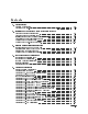
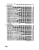
Troubleshooting the A11 5 dB Step Attenuator This assembly is a four-section 65 dB attenuator with 5 dB steps. It includes 5 dB, 10 dB, 20 dB, and 30 dB stages. The attenuator switching logic is provided by the A20 controller to the A19 power supply/YTF driver. A19 J10 supplies the logic to switch the attenuator along with the supply voltage. The following truth table may assist in troubleshooting the attenuator. The levels are being measured on U35. Table 7-3.
Troubleshooting the A12 RF Switch/A15 RF Switch and A21 Pin Switch/Diplexer Troubleshooting the A12 RF Switch/A15 RF Switch and A21 Pin Switch/Diplexer The A12 RF switch/A15 RF switch and A21 pin switch/diplexer troubleshooting has been grouped together because they are closely related. The A21 pin switch/diplexer routes the A11 5 dB step attenuator output to the rst converter for RF input frequencies from 100 Hz to 2.9 GHz, 1H- band. For RF input frequencies from 2.7 GHz to 26.
Troubleshooting the A14 YTF and A19 Power Supply/YTF Driver The A14 YTF and A19 power supply/YTF driver troubleshooting has been grouped together because they are closely related. The HP 70909A or HP 70910A RF section use a YIG Tuned Filter (YTF) for preselection from 2.7 GHz to 26.5 GHz. The HP 70910A RF section has a coaxial switch to bypass the YTF, while the HP 70909A RF section is always preselected.
Troubleshooting the A14 YTF and A19 Power Supply/YTF Driver During YTF alignment, the software sets the DACs to the following values while a coarse adjustment is done with A19R38 and A19R39. Delay 40 20 GHz Breakpoint 60 Preselector Peak 128 O set 128 Gain 128 The spectrum analyzer is set for a center frequency of 4.6786 GHz and a network analyzer is used to measure the center frequency of the YTF passband. The operator adjusts A19R38 until the YTF passband is within 65 MHz of 4.6786 GHz.
Troubleshooting the A14 YTF and A19 Power Supply/YTF Driver Power Supply Troubleshooting The A19 power supply/YTF driver contains the power supplies and driver circuits for the various assemblies of the module. The following power supplies are provided by A19 power supply/YTF driver J8: J8-1 +15 Vdc J8-3 +5 Vdc (Green LED DS2 should be on) J8-5 +8 Vdc J8-7 +7 Vdc J8-9 015 Vdc J8-11 +39 Vdc J8-13 ground If all the power supplies are down, check F1. If it is open, replace it.
Troubleshooting the A16 Preamp/Mixer Troubleshooting the A16 Preamp/Mixer The A16 preamp/mixer microcircuit is used when the modules input frequency is from 2.7 GHz (in 1L0 band) to 26.5 GHz. The RF input signal enters the microcircuit via J1 and is preampli ed prior to being harmonically mixed and down converted to a 321.4 MHz IF. The preampli er needs a +5 Vdc bias that is provided by A19 power supply/YTF driver. The A16 preamp/mixer contains pin diode switches that are biased to route the 3 GHz to 6.
Troubleshooting the A18 LO Leveling Ampli er The A18 LO leveling ampli er receives its biasing from the A19 power supply/YTF driver through J3. J3-1 gate bias is adjusted to the voltage printed on the A18 LO leveling ampli er. J3-5 and J3-6 supply +7 Vdc to the A18 LO leveling ampli er. J3-20 supplies +5 Vdc to A18 LO leveling ampli er. A19U12 is a dual DAC that adjusts the A18 LO leveling ampli er output power. Pin 6 controls which DAC is used.
Troubleshooting the A20 Controller Troubleshooting the A20 Controller (A) CPU BLOCK The A20 controller uses a Motorola 68000 microprocessor operating at 8 MHz. The clock is generated by a 16 MHz oscillator, U10, and is divided by 2 before it is used by the microprocessor. Pin 1 on U10 must be a TTL high to enable the oscillator. The microprocessor can also be halted if LRESET and LHALT are TTL lows. Both of these signals need to be TTL highs for the microprocessor to function properly.
Troubleshooting the A20 Controller (E) CONTROL LATCH Other functions of the A20 controller include turning on and o the 10 dB step gain, the YTF lter, and the active and error front panel LEDs. These control signals are latched by U4. These functions may be checked by con guring the module into a spectrum analyzer or using the Utilities available from the module veri cation software test menu. Select Utilities, then CHANGE DUT SETTINGS.
Performing Related Adjustments and Veri cation Tests Performing Related Adjustments and Veri cation Tests In the following section, all assemblies that require adjustments and veri cation tests are listed. Each assembly is followed by a list of adjustments and veri cation tests that must be performed to ensure proper operation after an assembly has been repaired, replaced, or adjusted.
Performing Related Adjustments and Veri cation Tests A4 18 dB isolator Perform the following related adjustments: None Perform the following related veri cation tests: All veri cation tests A5, A7, A8, A9 second converter Perform the following related adjustments: 2nd Converter Adjustments Perform the following related veri cation tests: All veri cation tests A6 programmable gain ampli er Perform the following related adjustments: Adjustment 02. 1st LO Power 2nd Converter Adjustments Adjustment 04.
Performing Related Adjustments and Veri cation Tests A19 power supply/YTF driver Perform the following related adjustments: All adjustments Perform the following related veri cation tests: All veri cation tests A20 controller Perform the following utility prior to any adjustments or veri cation tests: INITIALIZE ENTIRE FRONT END EEPROM Select Utilities, then WRITE DUT EEPROM. From this menu you can access the INITIALIZE ENTIRE FRONT END EEPROM utility.
Troubleshooting Utilities Menu This Troubleshooting Utilities menu is available through the Utilities menu, located at the bottom of the main module veri cation software test menu. Some parts of this menu are referred to during the troubleshooting procedures and are available here for reference.
Troubleshooting Utilities Menu --------------------------------------------------Menu for: CHANGE DUT RAM/DAC CONTENTS --------------------------------------------------EXIT THIS MENU CHANGE OFFSET DAC VALUE CHANGE GAIN DAC VALUE CHANGE DELAY DAC VALUE CHANGE PEAK DAC VALUE CHANGE BREAK POINT DAC VALUE CHANGE PGA DAC VALUE CHANGE PGA GAIN --------------------------------------------------Menu for: READ DUT ROM/EEPROM CONTENTS --------------------------------------------------EXIT THIS MENU DISPLAY EEPROM YT
Troubleshooting Utilities Menu 7-52 Troubleshooting
Overall Block Diagram of HP 70909A or HP 70910A RF section Overall Block Diagram of HP 70909A or HP 70910A RF section Front page for Foldout Goes Here (This is just a place holder.) Figure 7-6.
Overall Block Diagram of HP 70909A or HP 70910A RF section Back page for Foldout Goes Here (This is just a place holder.
8 Replacing Major Assemblies Overview In this chapter you will learn about: Each of the equipment setups used during module veri cation tests This chapter contains procedures for removal and replacement of major assemblies in your RF section. Note Because this service guide is part of an Option OB3 package which consists of two manuals, refer to Manual 2 of this option set for information on part listings and schematics.
Module Cover CAUTION This module contains components that can be damaged or destroyed by electrostatic discharge. It should be serviced at a static-safe workstation. For electrostatic discharge information, refer to \Preparing a Static-Safe Work Station" in Chapter 7. To Remove the Module Cover 1. Remove the four side screws (1). 2. Remove the four top screws (2). 3. Remove the module cover (3). To Replace the Module Cover 1. Replace the module cover (3). 2. Replace the four top screws (2) 3.
Module Cover Figure 8-1.
Front Panel CAUTION This module contains components that can be damaged or destroyed by electrostatic discharge. It should be serviced at a static-safe workstation. For electrostatic discharge information, refer to \Preparing a Static-Safe Work Station" in Chapter 7. Note Be careful not to bend the rigid coaxial cables or damage any center connector. To Remove the Front Panel 1. 2. 3. 4. 5. 6. Remove the module cover. (Refer to Figure 8-1.) Place A19 power supply/YTF driver in service position.
Front Panel Figure 8-2.
Rear Panel CAUTION This module contains components that can be damaged or destroyed by electrostatic discharge. It should be serviced at a static-safe workstation. For electrostatic discharge information, refer to \Preparing a Static-Safe Work Station" in Chapter 7. To Remove the Rear Panel 1. Remove the module cover. (Refer to Figure 8-1.) 2. Place A19 power supply/YTF driver in service position. (Refer to Figure 8-13.) 3.
Rear Panel Figure 8-3.
A2 RF First Converter CAUTION This module contains components that can be damaged or destroyed by electrostatic discharge. It should be serviced at a static-safe workstation. For electrostatic discharge information, refer to \Preparing a Static-Safe Work Station" in Chapter 7. To Remove the A2 RF First Converter 1. 2. 3. 4. 5. 6. 7. 8. 9. 10. 11. 12. 13. Remove the module cover. (Refer to Figure 8-1.) Place A19 power supply/YTF driver in service position. (Refer to Figure 8-13.
A2 RF First Converter Figure 8-4.
A5, A7, A8, A9 Second Converter CAUTION This module contains components that can be damaged or destroyed by electrostatic discharge. It should be serviced at a static-safe workstation. For electrostatic discharge information, refer to \Preparing a Static-Safe Work Station" in Chapter 7. These assemblies contain connector pins that can be easily damaged if proper alignment is not maintained when replacing the circuit cards. To Remove the A5, A7, A8, A9 Second Converter 1. 2. 3. 4. 5. 6. 7. 8. 9. 10. 11.
A5, A7, A8, A9 Second Converter Figure 8-5.
A6 Programmable Gain Ampli er CAUTION This module contains components that can be damaged or destroyed by electrostatic discharge. It should be serviced at a static-safe workstation. For electrostatic discharge information, refer to \Preparing a Static-Safe Work Station" in Chapter 7. To Remove the A6 Programmable Gain Ampli er 1. 2. 3. 4. 5. 6. 7. 8. 9. Remove the module cover. (Refer to Figure 8-1.) Place A19 power supply/YTF driver in service position. (Refer to Figure 8-13.
A6 Programmable Gain Ampli er Figure 8-6.
A10 Last Converter CAUTION This module contains components that can be damaged or destroyed by electrostatic discharge. It should be serviced at a static-safe workstation. For electrostatic discharge information, refer to \Preparing a Static-Safe Work Station" in Chapter 7. To Remove the A10 Last Converter 1. 2. 3. 4. 5. 6. 7. 8. 9. 10. Remove the module cover. (Refer to Figure 8-1.) Remove ten screws (1) and the cover (2). Remove the A6 programmable gain ampli er. (Refer to Figure 8-6.
A10 Last Converter Figure 8-7.
A11 5 dB Step Attenuator CAUTION This module contains components that can be damaged or destroyed by electrostatic discharge. It should be serviced at a static-safe workstation. For electrostatic discharge information, refer to \Preparing a Static-Safe Work Station" in Chapter 7. To Remove the A11 5 dB Step Attenuator 1. 2. 3. 4. 5. 6. 7. 8. Remove the module cover. (Refer to Figure 8-1.) Place A19 power supply/YTF driver in service position. (Refer to Figure 8-13.
A11 5 dB Step Attenuator Figure 8-8.
A12 RF Switch/A15 RF Switch (HP 70910A RF Section Only) CAUTION This module contains components that can be damaged or destroyed by electrostatic discharge. It should be serviced at a static-safe workstation. For electrostatic discharge information, refer to \Preparing a Static-Safe Work Station" in Chapter 7. To Remove the A12 RF Switch/A15 RF Switch 1. 2. 3. 4. 5. 6. 7. 8. 9. 10. 11. 12. Remove the module cover. (Refer to Figure 8-1.) Place A19 power supply/YTF driver in service position.
A12 RF Switch/A15 RF Switch (HP 70910A RF Section Only) Figure 8-9.
A14 YTF CAUTION This module contains components that can be damaged or destroyed by electrostatic discharge. It should be serviced at a static-safe workstation. For electrostatic discharge information, refer to \Preparing a Static-Safe Work Station" in Chapter 7. To Remove the A14 YTF 1. 2. 3. 4. 5. Remove the module cover. (Refer to Figure 8-1.) Place A19 power supply/YTF driver in service position. (Refer to Figure 8-13.) Remove the A20 controller. (Refer to Figure 8-15.
A14 YTF Figure 8-10.
A16 Preamp/Mixer CAUTION This module contains components that can be damaged or destroyed by electrostatic discharge. It should be serviced at a static-safe workstation. For electrostatic discharge information, refer to \Preparing a Static-Safe Work Station" in Chapter 7. To Remove the A16 Preamp/Mixer 1. 2. 3. 4. 5. 6. 7. 8. 9. 10. 11. 12. 13. 14. 15. Remove the module cover. (Refer to Figure 8-1.) Place A19 power supply/YTF driver in service position. (Refer to Figure 8-13.
A16 Preamp/Mixer Figure 8-11.
A18 LO Leveling Ampli er CAUTION This module contains components that can be damaged or destroyed by electrostatic discharge. It should be serviced at a static-safe workstation. For electrostatic discharge information, refer to \Preparing a Static-Safe Work Station" in Chapter 7. To Remove the A18 LO Leveling Ampli er 1. 2. 3. 4. 5. 6. 7. Remove the module cover. (Refer to Figure 8-1.) Place A19 power supply/YTF driver in service position. (Refer to Figure 8-13.
A18 LO Leveling Ampli er Figure 8-12.
A19 Power Supply/YTF Driver Service Position CAUTION This module contains components that can be damaged or destroyed by electrostatic discharge. It should be serviced at a static-safe workstation. For electrostatic discharge information, refer to \Preparing a Static-Safe Work Station" in Chapter 7. To place the A19 Power Supply/YTF Driver in the Service Position 1. Remove the module cover. (Refer to Figure 8-1.) 2. Remove three screws (1). 3.
A19 Power Supply/YTF Driver Service Position Figure 8-13.
A19 Power Supply/YTF Driver CAUTION This module contains components that can be damaged or destroyed by electrostatic discharge. It should be serviced at a static-safe workstation. For electrostatic discharge information, refer to \Preparing a Static-Safe Work Station" in Chapter 7. To Remove the A19 Power Supply/YTF Driver 1. 2. 3. 4. 5. 6. 7. 8. 9. Remove the module cover. (Refer to Figure 8-1.) Place A19 power supply/YTF driver in service position. (Refer to Figure 8-13.
A19 Power Supply/YTF Driver Figure 8-14.
A20 Controller CAUTION This module contains components that can be damaged or destroyed by electrostatic discharge. It should be serviced at a static-safe workstation. For electrostatic discharge information, refer to \Preparing a Static-Safe Work Station" in Chapter 7. To Remove the A20 Controller 1. 2. 3. 4. 5. 6. 7. 8. 9. Remove the module cover. (Refer to Figure 8-1.) Remove the SMB cable W14 (1) from A10 last converter J5 and A9 2nd LO PLL assembly J1.
A20 Controller Figure 8-15.
A22 Status CAUTION This module contains components that can be damaged or destroyed by electrostatic discharge. It should be serviced at a static-safe workstation. For electrostatic discharge information, refer to \Preparing a Static-Safe Work Station" in Chapter 7. To Remove the A22 Status 1. 2. 3. 4. 5. Remove the module cover. (Refer to Figure 8-1.) Remove the front panel assembly. (Refer to \Front Panel".) Disconnect the ribbon cable W4 (1) from A22 status J1. Remove four screws (2).
A22 Status Figure 8-16.
9 Overall Parts Identi cation Drawings Overview In this chapter you will learn about: Major cable reference designators and their associated HP part numbers Overall part locations through front, right, left, and rear veiws of your RF section This chapter contains information on all overall parts identi cation drawings that should be used when performing the troubleshooting procedures described in this service guide.
Major Cables and Assemblies Table 9-1. Cables for the HP 70909A RF Section and HP 70910A RF Section Cable Reference Designator HP Part Number W1 EMIM IF IN to A6J2 8120-5531 W2 Front Panel LO to A16J1 70909-20025 W3 Tune Span OUT to A19J7 8120-5027 W4 A20 to A22 harness 8120-5541 W5 RF IN to A11 Input 70909-20017 W6 2nd LO OUT to 2nd LO In 70909-20035 W7 A6J5 to A10J1 8120-5016 W8 A6J4 to A8J2 8120-5014 W9 A16 to A6J3 8120-5532 W10 A10 321.
Major Cables and Assemblies Table 9-1. Cables for the HP 70909A RF Section and HP 70910A RF Section (continued) Cable Reference Designator HP Part Number W31 A20 to A19J2 ribbon 8120-5539 W32 1st LO IN to A18 70909-20027 W33 AUX LO OUT to A18 70909-20028 W34 Tune + Span IN to A19J5 8120-5560 W35 Hughes connector assy 70909-60020 W36 A23 Limiter to A1 LPF 70909-20020 W37 A20J4 to A9J2 8120-5536 W38 A20J5 to A22J1 8120-5541 A11W1 Attenuator to A19J10 8120-5537 Table 9-2.
Major Cables and Assemblies Figure 9-1.
Major Cables and Assemblies Figure 9-2.
Major Cables and Assemblies Figure 9-3.
Major Cables and Assemblies Figure 9-4.
Major Cables and Assemblies Front View Identi cation Table 9-3. Overall Parts Identi cation Listing, Front View Item 1 2 3 4 5 6 7 8 9 10 11 12 HP Part Number 1250-1957 1810-0118 2190-0104 0590-1251 08673-60040 70909-00008 2950-0001 2190-0016 2190-0761 2190-0067 2950-0216 70909-00001 Description Adapter, SMA(f) to SMA(f) Termination, 50 ohm, SMA(f) Washer, Lock LK .439IN-ID Nut, Hex 15/32 - 32 Connector Assembly Panel, Front Dress Nut, Hex 3/8 - 32 Washer, Lock .377ID Washer, Flat .250ID Washer, Lock .
Right Side View Identi cation Right Side View Identi cation Table 9-4. Overall Parts Identi cation Listing, Right Side View Item 1 2 3 4 5 6 7 8 9 10 11 12 HP Part Number 0515-2332 0515-1521 70909-00002 0515-0433 0515-2126 70908-20019 0515-1038 0515-0664 0515-1992 0515-2126 0515-1427 0515-1084 Description Screw, SMM3.0 6 PCPNTX Screw, SMM3.0 5 FLTX Cover, Module Screw, SMM4.0 8 CWPNTX Screw, SMM3.0 6 CWPNTX Post, PC Support Screw, SMM3.0 35 CWPNTX Screw, SMM3.0 12 CWPNTX Screw, SMM2.
Right Side View Identi cation Figure 9-6.
Right Side View Identi cation Figure 9-7.
Right Side View Identi cation Figure 9-8.
Right Side View Identi cation Figure 9-9.
Left Side View Identi cation, Exploded Table 9-5. Overall Parts Identi cation Listing, Left Side View Exploded Item 1 2 3 4 5 6 7 8 9 10 HP Part Number 2950-0216 0515-2126 0515-0375 0515-0374 0515-0658 70904-20026 0515-2134 2950-0078 2190-0124 70909-20008 9-14 Overall Parts Identi cation Drawings Description Nut, Hex 1/4-36 Screw, SMM3.0 6 CWPNTX Screw, SMM3.0 16 CWPNTX Screw, SMM3.0 10 CWPNTX Screw, SMM2.0 6 CWPNTX Screw, SCREW-OSC FEED Screw, SMM3.0 10 CWPNTX Nut, Hex 10-32 Washer, Lock .
Left Side View Identi cation, Exploded Figure 9-10.
Left Side View Identi cation, Exploded Rear View Identi cation Table 9-6. Overall Parts Identi cation Listing, Rear View Item 1 2 3 4 5 6 7 8 9 HP Part Number 2190-0067 2950-0216 2950-0078 2190-0124 3050-1205 0515-2113 70908-20014 0515-2126 1810-0118 Description Washer, Lock .256ID Nut, Hex 1/4-36 Nut, Hex 10-32 Washer, Lock .195ID10 Washer, SH .190ID10 Screw, SMM4.0 8 PCPNTX Frame, Rear Screw, SMM3.0 6 CWPNTX Termination, 50 ohm, SMA(f) Figure 9-11.
Index 2 2nd converter adjustments, 5-10 4 42.8 MHz failure, 7-28 6 642.8 MHz failure, 7-28 A A10 last converter, 7-48 removal/replacement, 8-14 troubleshooting, 7-36 A11 5 dB step attenuator, 7-48 removal/replacement, 8-16 troubleshooting, 7-38 A1 2.
Adjustment 04. Last Converter Alignment, 5-39 Adjustment 05. PGA Calibration, 5-44 Adjustment 06.
Test 15. LO Input Amplitude Range, 7-28 Test 16. Microwave Image Rejection, 7-28 Test 17. EMIM Image Rejection, 7-28 Test 18. 2nd Converter Startup, 7-28 Test 19. Microwave Residual Responses, 7-29 Test 20.
S save TSCRIPT, 2-22 scalar network analyzer, specifying address, 2-21 serial number determining, 1-6 serial numbers power sensor, 3-19 serial numbers, module, 1-6 Series 300 computer, 2-3 service before beginning, 1-5 contacting Hewlett-Packard, 1-6 overview, 1-2 returning to Hewlett-Packard, 1-8 service position A19 power supply/YTF driver, 8-26 software available, 1-3 computer software required, 2-2 con guring, 2-11 entering DUT information, 3-3 installation, 2-5 loading, 3-2 purging, 2-10 TSCRIPT le, 2