
User`s guide


Chapter 4 109
Performance Tests
1. Conversion Loss
Performance Tests
1. Conversion Loss
Description
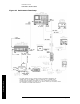
The conversion loss is checked at a nominal local-oscillator power level. A known input
power is applied to the input of the 11974. The IF output power is measured on an 8566B
Spectrum Analyzer. From the measurements, the conversion loss is calculated. The
calibration factors versus frequency of the millimeter-wave power-meter sensor and the
coupling factors versus frequency of the coupler are needed in this measurement.
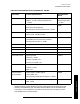
Procedure
1. Connect an SMA cable from the 1ST LO OUTPUT of the spectrum analyzer to the
INPUT of the 11975A Amplifier. Connect a second SMA cable to the OUTPUT of the
amplifier.
2. Connect the 8481A Power Sensor to the power-meter sensor cable, then zero and
calibrate the 436A Power Meter.
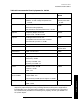
3. Set the spectrum analyzer controls as follows:
SHIFT ⇑ ⇑ ⇑ ⇑ (selects U Band)
FREQUENCY SPAN. . . . . . . . . . . . . . . . . . . . . . . . . . . . . . . . . . . . . . . . . . .0 Hz
CENTER FREQUENCY (sets the LO frequency to 5.0 GHz). . . . . . .50.3 GHz
CAUTION When you are using an 11975A Amplifier with an 11974, you must set the
amplifier rear-panel ALC switch to ON before you connect the amplifier to the
test setup. If the ALC switch is left in the OFF position, the amplifier output
power is high enough to destroy the mixer diodes.
4. On the 11975A Amplifier, set the rear-panel ALC switch to ON. Connect the 8481A
Power Sensor to the free end of the cable installed on the OUTPUT connector of the
amplifier listed in step 1. Set the 436A Power-Meter Cal Factor % to the appropriate
value for a frequency of 5 GHz.
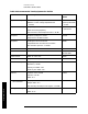
5. Adjust the amplifier OUTPUT POWER LEVEL for a reading of +15.2 dBm
±0.1 dBm on
the power meter.
6. Set the 432A Power Meter Cal Factor % to 100 percent.
7. Connect the equipment as shown in Figure 4-1 on page 106.