
User`s guide


Chapter 3 95
Operation
Using 8561A/62A/62B Spectrum Analyzers
Operation
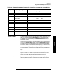
Table 3-9. Flatness Points and Conversion Losses for Frequencies above 18 GHz
Frequency
Band
Frequency Range (GHz) Number of
Flatness Points
Point
Spacing
Default
Conversion Loss
K 18.0 to 26.5 6 2 GHz 30 dB
A 26.5 to 40.0 8 2 GHz 30 dB
Q 33.0 to 50.0 7 3 GHz 30 dB
U 40.0 to 60.0 6 4 GHz 30 dB
V 50.0 to 75.0 6 5 GHz 30 dB
E 60.0 to 90.0 7 5 GHz 30 dB
W 75.0 to 110.0 8 5 GHz 30 dB
F 90.0 to 140.0 6 10 GHz 30 dB
D 110.0 to 170.0 7 10 GHz 30 dB
G 140.0 to 220.0 9 10 GHz 30 dB
Y 170.0 to 260.0 7 15 GHz 30 dB
J 220.0 to 325.0 8 15 GHz 30 dB
MARKER NORMAL
activates a single marker and places it at the center of the trace. This
softkey is also annotated as
MARKER DELTA, if delta-marker mode
has been previously activated by the
MARKER DELTA softkey under
the Marker menus.
If one marker is already on, no operation takes place. If two markers
are on (as in
MARKER DELTA mode), pressing MARKER DELTA deletes
the anchor marker and makes the active one the new, single marker.
The marker reads the amplitude and the frequency (or relative time,
when the frequency span equals 0 Hz), and displays these values in
the active function block and in the upper-right corner of the display.
To move the marker, use either the knob, the step keys, or the data
keys.
The marker reads data from the currently active trace. (An active
trace is one that is in either the clear-write or max-hold mode; this
may be either trace A or trace B.) If both traces are active, or if both
traces are in view mode, the marker reads data from trace A.
PEAK SEARCH
places a marker on the highest point on a trace. The frequency and
amplitude of the marker are displayed in the upper-right corner of
the screen;
PEAK SEARCH does not alter the active function.