
Technical data

32 7000 Series Oscilloscopes Service Guide
2 Testing Performance
oscilloscope to set the threshold test settings as shown in
Table 5.
8 Do the following steps for each of the threshold voltage levels
shown in Table 5.
a Set the threshold voltage shown in the User softkey using
the Entry knob on the oscilloscope.
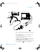
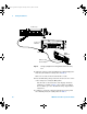
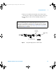
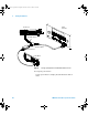
b Enter the corresponding DC offset voltage on the
oscilloscope calibrator front panel. Then use the
multimeter to verify the voltage.
Digital channel activity indicators are displayed on the
status line at the top of the oscilloscope display. The
activity indicators for D7-D0 should show all of the
channels at digital high levels.
c Use the knob on the oscilloscope calibrator to decrease the
offset voltage, in increments of 10 mV, until the activity
indicators for digital channels D7-D0 are all at digital low
levels. Record the oscilloscope calibrator voltage in the
Performance Test Record (see page 57).
d Use the knob on the oscilloscope calibrator to increase the
offset voltage, in increments of 10 mV, until the activity
indicators for digital channels D7-D0 are all at digital high
levels. Record the oscilloscope calibrator voltage in the
Performance Test Record (see page 57).
Table 5 Threshold Accuracy Voltage Test Settings
Threshold voltage
setting
(in oscilloscope User
softkey)
DC offset voltage setting
(on oscilloscope
calibrator)
Limits
+5.00 V +5.250 V ±1 mV dc Lower limit = +4.750 V
Upper limit = +5.250 V
–5.00 V –4.750 V ±1 mV dc Lower limit = –5.250 V
Upper limit = –4.750 V
0.00 V +100m V ±1 mV dc Upper limit = +100 mV
Lower limit = –100 mV
7000 service guide.book Page 32 Thursday, October 16, 2008 12:18 PM