
Technical data
Testing Performance 2
7000 Series Oscilloscopes Service Guide 33
Before proceeding to the next step, make sure that you have
recorded the oscilloscope calibrator voltage levels for each of
the threshold settings shown in Table 5.
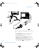
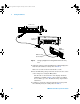
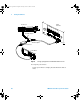
9 Use the 8-by-2 test connector to connect digital channels
D15-D8 to the output of the oscilloscope calibrator. Then
connect the D15-D8 ground lead to the ground side of the
8-by-2 connector.
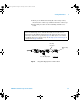
10 Repeat this procedure (steps 6 through 8) for digital channels
D15-D8 to verify threshold accuracy and record the threshold
levels in the Performance Test Record (see page 57). Be sure
to set the thresholds with the User softkey for the appropriate
set of channels.
To verify voltage measurement accuracy
This test verifies the accuracy of the analog channel voltage
measurement for each channel. In this test, you will measure
the dc voltage output of an oscilloscope calibrator using dual
cursors on the oscilloscope, and compare the results with the
multimeter reading.
Test limits: ±2.0% of full scale ±1 LSB*
• Full scale is defined as 32 mV on the 2 mV/div range.
• Full scale on all other ranges is defined as 8 divisions times
the V/div setting.
*1 LSB = 0.4% of full scale
7000 service guide.book Page 33 Thursday, October 16, 2008 12:18 PM