
Technical data


Troubleshooting 4
7000 Series Oscilloscopes Service Guide 77
To check the 7000A Series oscilloscope power supply
1 Disconnect the power cord from the oscilloscope. Then
remove the oscilloscope cover.
2 Connect the negative lead of the multimeter to a ground
point on the oscilloscope.
3 Connect the power cord and turn on the oscilloscope.
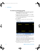
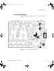
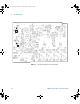
4 Measure the power supply voltage at J3200, pin 9 on the
system board. See Figure 12 on page 75. The voltage should
be 15 V ±10%.
• If the voltage is not correct, continue to the next step.
• If the voltage is correct, the power supply is good.
5 Disconnect the cable from the system board and check the
voltage between pins 9 & 5 of the connector coming from the
power supply.
6 If it is less than 14 V, the problem is in the cable or the power
supply. Remove the cable and test it for shorts or opens using
the DMM. Replace the defective assembly.
7 If the voltage is 15 V ±10% only when the cable is
disconnected from the system board, then test the system
board.
CAUTION
USE AN EXTERNAL FAN TO AVOID OVERHEATING COMPONENTS !
When you remove the oscilloscope cover and main shield, use an external fan to
provide continuous air flow over the heat sinks. Air flow over the heat sinks is
reduced when the cover and main shield are removed, which leads to higher than
normal operating temperatures. Have the fan blow air across the system board
where the heat sinks are located. Otherwise, damage to the components can
occur.
If the cover of a 7000A Series oscilloscope is removed but the main shield remains
installed and the bottom holes are not blocked, the instrument will cool properly.
7000 service guide.book Page 77 Thursday, October 16, 2008 12:18 PM