
Technical data

27
Agilent InfiniiVision 7000B Series Oscilloscopes
Evaluation Guide
4
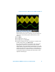
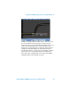
Using Pass/Fail Mask Testing to
Discover a Signal Violation
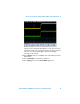
With mask testing you can set up a pass/fail test criteria for automatically
testing waveforms to see if they conform to specific wave shapes. In this lab
we will test a digital signal that includes an infrequent glitch. With
InfiniiVision’s hardware-based mask testing capability, we will be able to test
up to 100,000 waveforms per second and gain insight into the statistical
occurrences of this particular glitch. To enable Mask Testing, your
oscilloscope must have the mask test option (Option LMT) installed. You can
verify the installed options on your oscilloscope at [Utility] > Service >
About Oscilloscope.
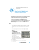
Setup
1 Connect the demo kit’s 40-pin ribbon cable from the back of the Agilent
InfiniiVision Series oscilloscope to the 40-pin connector on the demo
board.
2 Connect channel 1 probe to the CH1 test point and ground (GND).
3 Connect channel 2 probe to the CH2 test point and ground (GND).
4 Set the rotary switch on the demo board for the Data w/ Glitch signal
(Mode #2).
5 Press [Default Setup].
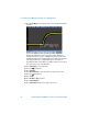
6 Set the channel 1 vertical scale to
500 mV/div and the vertical offset to
1.0 V.
7 Push the Trigger Level knob to set the
trigger level at 50%.
8 Set the timebase to 20 ns/div.
9 Set the waveform intensity to 100%
using the Waveform Intensity knob (full clockwise).
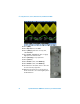
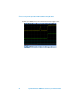
10 Press [Analyze].
11 Press Features Mask two times to turn on mask testing.
12 Press Automask.