
Technical data

43
Agilent InfiniiVision 7000B Series Oscilloscopes
Evaluation Guide
8
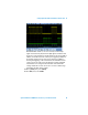
Verifying RS-232/UART Serial Bus
Communication
The RS-232 and UART serial buses are typically used to communicate
between a CPU/MCU and peripheral devices such as printers, storage
devices, and/or EEPROM programmers. The bus consists of separate trans-
mit and receive signals and the clock is embedded in these signals. The
RS-232/UART bus is very flexible in terms of user-definable baud rates, num-
ber of bits, bit polarity, bit order, and parity. Each of the parameters can be
defined on the Agilent InfiniiVision Series oscilloscope for triggering and
decoding this bus. You can also use the RS-232/UART trigger and decode
option on many RS-485 applications because the RS-485 specification is an
electrical specification only; not a protocol specification. To enable
RS-232/UART decode and triggering, your oscilloscope must have the
RS-232/UART serial bus decode option (Option 232) installed. You can verify
the installed options on your oscilloscope at [Utility] > Service > About
Oscilloscope.
Setup
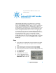
1 Connect the demo kit’s 40-pin ribbon cable from the back of the Agilent
InfiniiVision Series oscilloscope to the 40-pin connector on the demo
board.
2 Connect channel 1 probe to the CH1 test point and ground (GND).
3 Connect channel 2 probe to the CH2 test point and ground (GND).
4 Set the rotary switch on the demo board for the RS-232 signal (Mode #7).
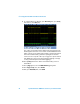
5 Press [Default Setup].
6 Press [Auto Scale].
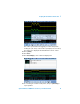
7 Set the timebase to 1.0 ms/div.
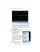
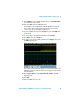
8 To turn on UART/RS-232 decode,
first press [Serial]; then, select the
UART/RS232 serial decode mode.