
Technical data

8 Verifying RS-232/UART Serial Bus Communication
44 Agilent InfiniiVision 7000B Series Oscilloscopes Evaluation Guide
9 To configure the bus for odd parity, press Bus Config; then, press Parity
three times to select Odd parity.
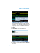
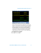
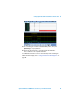
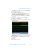
The oscilloscope should now be decoding both the transmit and receive
RS-232 signals in hex format. Let’s now turn on default RS232 waveform
labels so that we can see which analog channel is capturing the transmit
data stream and which analog channel is capturing the receive data
stream. Let’s also set up the oscilloscope to trigger on a specific transmit
byte (0x4D). The oscilloscope should currently be triggering on an edge
crossing of channel 2 (Auto Scale default triggering).
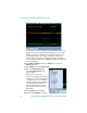
10 Press [Label] (between the channel 1 and channel 2 keys) to turn on
default labels.
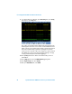
11 Press [Trigger]; then, select the UART/RS232 triggering mode.
12 Press Trigger Setup; then, select Tx Data.
13 Next, press Data 0x00; then, select 0x4D.