
Technical data

Verifying CAN Serial Bus Communication 9
Agilent InfiniiVision 7000B Series Oscilloscopes Evaluation Guide 51
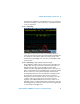
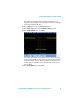
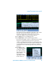
verify that these signals have correlated values. So let’s stop acquisitions
and “freeze” the display in order to verify a time-correlated measurement
on just one acquisition.
22 Press [Run/Stop].
You should now see that the hex value of the parallel bus (Bus1) is
exactly the same as the hex value of the data byte within the CAN decode
trace. And, both of these directly relate to the average voltage of the
channel 2 input signal (Avg(2)). Let’s now see if our CAN signal includes
any error frames.
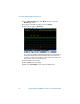
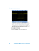
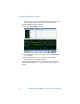
23 Press [Run/Stop] to begin repetitive acquisitions again.
Notice within the serial decode trace at the bottom of the display a red
flashing “ERR” message near the end of the frame/packet. This is an
indication that the oscilloscope is detecting error frames. With
hardware-based decoding, Agilent InfiniiVision Series oscilloscopes are
able to capture infrequent errors and display them on-screen very quickly.
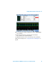
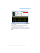
All other oscilloscopes on the market today utilize software-based
decoding which tends to be slow, especially when using deep memory.
This means that critical information can be missed, such as these
infrequent error frames. Now that we know our system has errors, let’s
set up the oscilloscope to trigger on just error frames, instead of
triggering on frame ID:07F. However, because the error frames on our
CAN demo signal occur relatively infrequently, we will need to select the
Normal trigger mode to prevent the oscilloscope from auto triggering due
to a low repetition rate trigger event.