
User`s guide


Initial Setup 2
InfiniiVision Oscilloscopes User’s Guide 61
Channel Coupling and Input Impedance Selection
3 Press the channel’s on/off key, then press the Coupling softkey to select the input
channel coupling.
Coupling changes the channel's input coupling to either AC (alternating current) or DC
(direct current). AC coupling places a 3.5 Hz high-pass filter in series with the input
waveform that removes any DC offset voltage from the waveform. When AC is
selected, “AC” is illuminated on the front panel next to the channel position knob ( ).
• DC coupling is useful for viewing waveforms as low as 0 Hz that do not have large
DC offsets.
• AC coupling is useful for viewing waveforms with large DC offsets. When AC
coupling is chosen, you cannot select 50 mode. This is done to prevent damage
to the oscilloscope.
Note that Channel Coupling is independent of Trigger Coupling. To change trigger
coupling see page 87.
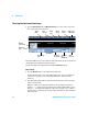
4 Press the Imped (impedance) softkey.
The analog channel input impedance can be set to either 1M Ohm or 50 Ohm by
pressing the Imped softkey.
• 50 Ohm mode matches 50-ohm cables commonly used in making high frequency
measurements, and 50-ohm active probes. This impedance matching gives you the
most accurate measurements since reflections are minimized along the signal
path. When 50 Ohm is selected, “50” is illuminated on the front panel next to the
channel position knob. The oscilloscope automatically switches to 1 M Ohm mode
to prevent possible damage if AC coupling is selected.
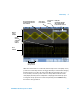
Measurement Hints
If the channel is DC coupled, you can quickly measure the DC component of the signal by simply
noting its distance from the ground symbol.
If the channel is AC coupled, the DC component of the signal is removed, allowing you to use
greater sensitivity to display the AC component of the signal.
NOTE
When you connect an AutoProbe, self-sensing probe, or a compatible InfiniiMax probe,
the oscilloscope will automatically configure the oscilloscope to the correct impedance.