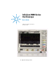
Infiniium 9000 Series Oscilloscope User’s Guide Publication number 54904-97008 November 2012 © Agilent Technologies 2012
In This Book This book provides the information you need to begin using the Infiniium 9000 Series oscilloscope. It contains four chapters: Chapter 1, “Setting Up the Oscilloscope”, contains inspection, power requirements, air flow, and setup information. Chapter 2, “Working in Comfort”, contains recommendations for working comfortably and safely while operating the Infiniium oscilloscope.
9000 Series Oscilloscopes -- At a Glance 9000 Series Oscilloscopes -- At a Glance 9000 Series Oscilloscope Models Model Bandwidth Std. Memory (2 ch, 4 ch) DSO/MSO9064A DSO/MSO9104A DSO/MSO9254A DSO/MSO9404A DSO9024H DSO9054H DSO9104H DSO9204H 600 MHz 1 GHz 2.
9000 Series Oscilloscopes -- At a Glance • Graphical interface menus and toolbars simplify complex measurement setups. Horizontal controls set sweep speed and position • Main sweep speeds from 5 ps/div to 20 s/div. • Intensified waveforms on main sweep window make it easy to see what will appear in the zoom window. Acquisition and general controls start and stop the scope and do basic setup • Run and stop controls for continuous or single acquisitions. • Clear display before one or more acquisitions.
Contents 9000 Series Oscilloscopes -- At a Glance 3 1 Setting Up the Oscilloscope To inspect package contents 9 To inspect options and accessories 10 Technical Specifications 11 To position for proper airflow 12 To connect power 14 To connect a mouse, keyboard, LAN cable, USB device, and printer To connect oscilloscope probes 17 To tilt the oscilloscope for easier viewing 19 To turn on the oscilloscope 20 To turn off the oscilloscope 21 To verify basic oscilloscope operation 22 Installing application pro
Contents To clear the waveform display 67 To print the screen 68 To change waveform brightness 69 To turn a channel on or off 70 To adjust the vertical offset 71 To adjust vertical scaling 73 To access the channel setup 74 To set the horizontal reference point 75 To adjust horizontal scale 76 To adjust horizontal position 77 To access the horizontal setup 78 To zoom on a section of the waveform 79 To move the markers using the graphical interface To make a measurement on a waveform 82 To access the trigger
1 Setting Up the Oscilloscope
Setting Up the Oscilloscope This chapter shows you how to set up your Infiniium oscilloscope, connect power and accessories, and verify general operation.
Setting Up the Oscilloscope To inspect package contents ❏ Inspect the shipping container for damage. Keep a damaged shipping container or cushioning material until you have inspected the contents of the shipment for completeness and have checked the oscilloscope mechanically and electrically. ❏ Inspect the oscilloscope. • If there is mechanical damage or a defect, or if the oscilloscope does not operate properly or does not pass performance tests, notify your Agilent Technologies Sales Office.
Setting Up the Oscilloscope To inspect options and accessories Verify that you received the options and accessories you ordered and that none were damaged. If anything is missing, contact your nearest Agilent Technologies Sales Office. If the shipment was damaged, or the cushioning materials show signs of stress, contact the carrier and your Agilent Technologies Sales Office.
Setting Up the Oscilloscope Technical Specifications For complete specifications and characteristics, direct your web browser to www.agilent.com and perform a search for the oscilloscope’s model number. Then select “Data Sheets” from the Library.
Setting Up the Oscilloscope To position for proper airflow CAUTION Position the oscilloscope where it will have sufficient clearance for airflow around the top, back, and sides (see Figure 1-1). Place the oscilloscope on a hard surface to avoid blocking the airflow underneath the oscilloscope. (For example, a piece of paper or carpet could block the fans and cause the instrument to overheat.
Setting Up the Oscilloscope Figure 1-1 Minimum top clearance 0 mm Infiniium 9000 Series oscilloscope (front view) Minimum bottom clearance: No intrusion into the space under the oscilloscope as defined by the feet. Feet must rest on hard surface. Rear Panel Minimum 75 mm Minimum 25.4 mm Minimum 25.
Setting Up the Oscilloscope To connect power 1 Position the oscilloscope so that it is not difficult to unplug the power cord. 2 Connect the power cord to the side panel of the oscilloscope and then to a suitable ac voltage source (100 to 120 V, 50/60/400 Hz and 100 to 240 V, 50/60 Hz for the 9000 series). The power cord serves as the main disconnecting device. The maximum power dissipation is 375 W. The oscilloscope power supply automatically adjusts for line input voltages in the range 100 to 240 VAC.
Setting Up the Oscilloscope To connect a mouse, keyboard, LAN cable, USB device, and printer See Figure 1-2 on the next page for the location of the side panel connectors described below. Mouse The mouse can be plugged into either a USB port or into a PS2 port. There are several USB connectors on the front panel or the side panel of the oscilloscope that can be used.
Setting Up the Oscilloscope Figure 1-2 Mouse PS/2 port Keyboard PS/2 Port Removable Hard Drive Serial printer port XGA video output Parallel printer port USB ports LAN port USB cable AC power input Side Panel 16
Setting Up the Oscilloscope To connect oscilloscope probes 1 Attach the probe connector to the desired oscilloscope channel or trigger input using the probe instructions.
Setting Up the Oscilloscope 2 Connect the probe to the circuit of interest using the browser or other probing accessories. Figure 1-4 Probing the Circuit 3 Disconnect the probe. CAUTION CAUTION Do not attempt to twist the snap-on probes on or off the oscilloscope’s BNC connector. Twisting the probe connector body will damage it. ! Do not exceed the maximum input voltage rating.
Setting Up the Oscilloscope To tilt the oscilloscope for easier viewing 1 Lift up the front of the oscilloscope, grasp one of the plastic feet on either side, and pull it down and forward until it latches into place. Repeat for the other foot.
Setting Up the Oscilloscope To turn on the oscilloscope The first time you turn on the oscilloscope, you will need to have a mouse connected. The mouse is needed to accept the Microsoft end-user license agreement for the Windows 7 operating system. 1 Press the power switch in the lower left corner of the oscilloscope front panel. Figure 1-6 power switch Turning on the Oscilloscope After a short initialization period, the oscilloscope display appears. The oscilloscope is ready to use.
Setting Up the Oscilloscope To turn off the oscilloscope 1 Press the power switch at the lower left corner of the oscilloscope front panel. The oscilloscope will go through a normal Windows operating system shutdown process.
Setting Up the Oscilloscope To verify basic oscilloscope operation 1 Connect one end of the passive probe cable channel 1. 2 Connect the other end of the passive probe cable to the front panel probe comp connector with the square wave label. Figure 1-7 Front panel connector with square wave label Verifying Basic Oscilloscope Operation 3 Press the [Default Setup] key on the front panel. The display will pause momentarily while the oscilloscope is configured to its default settings.
Setting Up the Oscilloscope The display will pause momentarily while the oscilloscope adjusts the sweep speed and vertical scale. You should then see a square wave with peak-to-peak amplitude of approximately 5 divisions and about four cycles on screen. If you do not see the waveform, ensure your power source is adequate, the oscilloscope is properly powered-on, and the probe is connected securely to the front panel connector.
Setting Up the Oscilloscope Installing application programs on Infiniium Infiniium is an open Windows operating system, which allows you to install your own application software. Agilent has verified that the following applications are compatible with the Infiniium oscilloscope application.
Setting Up the Oscilloscope Changing Windows Operating System Settings Before changing any Windows operating system settings outside of the oscilloscope application you should exit the oscilloscope application. • • • • • • • Many Windows operating system settings can be changed to suit your own personal preferences. However, some operating system settings should not be changed because doing so would interfere with the proper operation of the oscilloscope. Do not change the Power Options.
Setting Up the Oscilloscope To clean the oscilloscope Clean the oscilloscope with a soft cloth dampened with a mild soap and water solution. CAUTION Do not use too much liquid in cleaning the oscilloscope. Water can enter the Infiniium front panel, damaging sensitive electronic components.
2 Working in Comfort
Working in Comfort To optimize your comfort and productivity, it is important that you set up your work area correctly and use your Infiniium oscilloscope properly. With that in mind, we have developed some setup and use recommendations for you to follow based on established ergonomic principles. Improper and prolonged use of keyboards and input devices are among those tasks that have been associated with repetitive strain injury (RSI) to soft tissues in the hands and arms.
Working in Comfort About Repetitive Strain Injury What is RSI? What causes RSI? What if I experience discomfort? Because your comfort and safety are our primary concern, we strongly recommend that you use the Infiniium oscilloscope in accordance with established ergonomic principles and recommendations.
Working in Comfort Mice and Other Input Devices Various aspects of using mice and other input devices may increase your risk of discomfort or injury. Observing the following recommendations may reduce that risk. • Try to keep your hand, wrist, and forearm in a neutral position while using your mouse or other input device. • If you use your thumb to rotate the ball on a trackball or spaceball, keep it in a relaxed, natural shape, and maintain a neutral posture in your hand, wrist, and forearm.
3 Using the Oscilloscope
Using the Oscilloscope The topics covered in this chapter are very basic controls. For more detailed explanations of controls not found in this chapter, consult the built-in information system loaded on your oscilloscope (Help > Contents). The Infiniium Oscilloscope is designed to be easy to use. • The familiar front-panel oscilloscope interface with knobs and keys is optimized for the most common kinds of troubleshooting tasks and basic measurements. See “Using the Front Panel”.
Using the Oscilloscope Using the Front Panel The Infiniium 9000 oscilloscope front panel gives you direct access to the functions needed to perform the most common measurements, using a traditional oscilloscope interface. Knobs and keys let you directly set vertical and horizontal parameters. In addition, the front panel has a set of LED (LightEmitting Diode) indicators; by using these and the display, you see the oscilloscope’s configuration at a glance.
Using the Oscilloscope Front Panel Figure 3-1 shows a typical Infiniium 9000 Series oscilloscope front panel. Figure 3-1 Selection knob (push to toggle selection) Run/Stop control section Horizontal controls (time/div, position, etc.
Using the Oscilloscope Using the front panel, you can configure the oscilloscope for most troubleshooting tasks.
Using the Oscilloscope Acquisition Run Controls Using the acquisition run controls, you control whether the oscilloscope is running or stopped. You can also put the oscilloscope into Single mode where only one acquisition is acquired before the oscilloscope stops. Horizontal Controls Using the horizontal controls, you configure the oscilloscope’s horizontal scale (time per division) and horizontal position of the waveform.
Using the Oscilloscope Vertical Controls Using the vertical controls, you set the vertical scaling (volts per division) and vertical offset. You can also turn the display on or off for a particular channel. Additionally, this section has a set of LEDs per channel that tell you what the input impedance is for the channel, what the coupling is for the channel, and whether or not Bandwidth Limit is enabled.
Using the Oscilloscope To set the oscilloscope to a known starting condition • Press the [Default Setup] key. You can set up the oscilloscope for many different kinds of complex measurements. To easily reset the oscilloscope to a known measurement configuration, use the [Default Setup] key. If you use the [Default Setup] key, you can select Control > Undo Default Setup to return the oscilloscope to its original configuration.
Using the Oscilloscope To start and stop waveform acquisition The [Run/Stop] key is green when the oscilloscope is acquiring data, and red when it is stopped. • To start a waveform acquisition, press the [Run/Stop] key. The oscilloscope begins acquiring data. When it receives a trigger signal, it finishes acquiring data, updates the display, then starts another acquisition cycle if it is in triggered (Trig’d) or auto trigger (Auto) mode. • To stop waveform acquisition, press the [Run/Stop] key.
Using the Oscilloscope To clear the waveform display • Press the [Clear Display] key. The oscilloscope clears the waveform display. If the oscilloscope is in Run mode and is receiving triggers, it will update the display as it collects new waveform data. Clearing the waveform display also resets averaging, infinite persistence, color grade persistence, histogram, mask testing, and measurement statistics.
Using the Oscilloscope To turn an analog channel on or off • To turn an analog channel on, press the channel number key in the Vertical section until it is illuminated. To turn it off, press the channel number key again. If you are not using a particular analog channel, you can turn it off. This simplifies the waveform display and also increases the display update rate. While an analog channel is turned off, data acquisition continues for that analog channel.
Using the Oscilloscope To turn the digital channels on or off • To turn the digital channels on, press the [Digital] key on the front panel. To turn them off, press the key again.
Using the Oscilloscope To adjust the analog channel’s vertical scale and offset • To make the waveform bigger, turn the vertical scale knob clockwise. To make it smaller, turn the knob counter-clockwise. The vertical scale knob is the larger of the two knobs for a channel. It is marked with a set of sine wave symbols. Decreasing the vertical scale makes the waveform bigger. There are fewer volts displayed per division. Increasing the vertical scale makes the waveform smaller.
Using the Oscilloscope To adjust horizontal scale and horizontal position • To stretch the waveform horizontally, turn the horizontal scale knob clockwise. To shrink it horizontally, turn the knob counter-clockwise. The horizontal scale knob is the larger of the two horizontal control knobs. It is marked with a set of sine wave symbols. Stretching the waveform means there are fewer seconds displayed per division. Shrinking the waveform means there are more seconds displayed per division.
Using the Oscilloscope To magnify a part of the waveform using Zoom • To turn on zoom, press the [Zoom] key. To turn it off, press the [Zoom] key again. The waveform display area splits into two regions. The top one is the main timebase. The bottom is the zoomed timebase, which represents a software expansion of the acquired waveform data. A section of the waveform in the main sweep window is highlighted to indicate the part shown in the delayed sweep window.
Using the Oscilloscope To set the oscilloscope to trigger on an edge 1 Press and release the [Source] key until the desired source LED is illuminated. You can choose any of the channels, the Aux, or Line as the source for an edge trigger. 2 Press the [Slope] key until the desired slope LED is illuminated. You can have an edge trigger on a rising or falling edge. 3 Press the [Sweep] key until the Trig’d LED is illuminated. The oscilloscope will wait for the edge before initiating a sweep.
Using the Oscilloscope To use the markers • • • • Markers make it easier to make precise measurements because the marker measurement readouts show exact voltage and time positions for the markers. The measurements are based on actual waveform data from the acquisition system, not on approximations based on the display position, so you can be sure that the values are highly accurate.
Using the Oscilloscope To use the quick measurements The action taken when the [Multi Purpose] key is pressed depends on the feature selected in the Customize Multipurpose dialog box. The default feature is QuickMeas (quick measurements), which is described as follows. • To turn on the quick measurement display, press the [Multi Purpose] key. The five preset measurements defined in the Quick Measurement configuration are enabled and results are displayed on the screen for the first waveform source.
Using the Oscilloscope To enable or disable the touch screen • To enable or disable the touch screen, press the front panel [Touch] key.
Using the Oscilloscope Using the Graphical Interface With the graphical interface for the Infiniium Oscilloscope, you can access all the configuration and measurement features of the oscilloscope through an easy-to-use system of menus, tool bars, dialog boxes, icons, and buttons.
Using the Oscilloscope Graphical User Interface The graphical interface looks like the following two figures.
Using the Oscilloscope Figure 3-3 Single See more measurements Turn off any measurements that are running (use Clear display to reset/restart measurement statistics) Run Stop Clear display Print screen Set horizontal scale Access the Horizontal Setup dialog box Set horizontal position (delay) Access the Trigger Setup dialog box Set trigger level Waveform Brightness Infiniium Oscilloscope Bottom of Display To make it easy to see which controls affect each waveform, the oscilloscope uses color cons
Using the Oscilloscope particular measurement situation. For example, it might be easiest to set a coarse vertical scale using the knobs, then fine-tune the setting using the graphical user interface. The graphical interface is arranged so that the most common functions affecting the waveform display are located around the edge of the waveform viewing area. These include the measurement toolbar, horizontal and trigger toolbar, and vertical toolbar.
Using the Oscilloscope Other Measurement Features More measurements are available than will fit on a single toolbar. Click the More (1 of 2) or More (2 of 2) icons to see other measurements. Clicking Delete All will remove all selected measurements from the waveform display area. Tab Display Area The tab display area is located beneath the waveform viewing area.
Using the Oscilloscope scaling and offset and the horizontal scale and position to present the zoomed section of the waveforms. See “To zoom on a section of the waveform”. Avoid Overdriving Vertical Input Amplifiers When zooming on a waveform with the oscilloscope running, be careful to keep the signal within the screen vertically to avoid overdriving the vertical input amplifiers. Overdriving causes waveform distortion and erroneous measurement results.
Using the Oscilloscope Horizontal and Trigger Toolbar At the bottom of the waveform display area is the horizontal and trigger toolbar. This includes the run/stop controls, the horizontal controls, and the trigger controls. Run/Stop Control See figure 3-11. At the left side of the Horizontal and Trigger toolbar bar are six icons: • The leftmost is a blue-green octagon. Clicking this starts an acquisition. (Same as pressing the [Run] key on the front panel.) • The next control is a red octagon.
Using the Oscilloscope is post-trigger. • Right means the information on the display is pretrigger. The horizontal position value represents the time relative to the trigger at the respective horizontal reference. When you change the horizontal scale, the waveforms expand and contract about this reference position. Trigger settings and controls The right side of the Horizontal and Trigger toolbar contains the trigger settings and controls.
Using the Oscilloscope To perform basic user interface operations • To move the pointer on the screen, move the mouse or touch the screen with the stylus and move it. • To click an item in the graphical interface, point at that item with the pointer, then press and release the left mouse button or touch screen. • To right-click an item in the graphical interface, point at that item with the mouse pointer, then press and release the right mouse button.
Using the Oscilloscope Figure 3-5 Click and drag the title bar to move the dialog box on the screen Click to put a check mark in the check box and enable Connect Dots mode Click one of these check boxes to select Color Grade or Infinite persistence Click and drag the Intensity control slider up to increase the waveform brightness Click and drag the Intensity control slider down to decrease the waveform brightness Dialog Box Interface Elements 59
Using the Oscilloscope Figure 3-6 Click one of these Close buttons to close the dialog box click one of these option buttons to change the number of waveform viewing areas Click and drag the Intensity control slider up to increase the intensity of the grid Click and drag the Intensity control slider down to decrease the intensity of the grid Click this check box to enable the touch screen Dialog Box Interface Elements 60
Using the Oscilloscope Figure 3-7 Click the arrow in a drop-down list box... ...
Using the Oscilloscope To select a command from the menu bar 1 Click a menu bar item. 2 Move the pointer to the desired menu item. 3 Click the mouse button or touch screen. The desired command is executed, or a dialog box is presented for you to configure the oscilloscope. If you continue to hold the mouse button after step 1, release the button in step 3 to execute the command. Some menus have submenus. These are indicated by an arrow at the right side of the command.
Using the Oscilloscope To select a command from a context-sensitive menu 1 Move the mouse pointer to a particular area of the display in which you want to change the oscilloscope configuration. Context-sensitive menus provide quick access to commands and configuration items that relate only to the context of the particular graphical interface item in which they are found.
Using the Oscilloscope Figure 3-9 Right-click the mouse in the waveform display area, then select Autoscale from the menu to force the oscilloscope to autoscale the current waveform(s) Selecting a Command from a Context-Sensitive Menu 64
Using the Oscilloscope Figure 3-10 Right-click in this region to see the Acquisition Setup context-sensitive menu Right-click in this region to see the Measurement Setup context-sensitive menu Right-click in the waveform display area to see the waveform contextsensitive menu Right-click in this region to see the horizontal, trigger, and run controls context-sensitive menu Right-click in this region to see the contextsensitive menu for the currently selected tab Location of Context-Sensitive Menus 65
Using the Oscilloscope To start and stop waveform acquisition • To start waveform acquisition, click the start button at the bottom of the waveform display area. • To stop waveform acquisition, click the stop button at the bottom of the waveform display area. See figure 3-11. You can still use the [Run/Stop] key on the front panel.
Using the Oscilloscope To clear the waveform display • Click the clear display button at the bottom of the waveform display. See figure 3-12. You can still use the [Clear Display] key on the front panel while the graphical interface is enabled. Clearing the display removes all displayed waveform data in preparation for another acquisition. It also resets all automatic measurements and measurement statistics.
Using the Oscilloscope To print the screen • Click the print button at the bottom of the waveform display. See figure 3-13. Infiniium prints the screen to the default printer according to the configuration that you have selected in the Windows Control Panel.
Using the Oscilloscope To change waveform brightness • Click the waveform brightness button at the bottom of the waveform display. See figure 3-14.
Using the Oscilloscope To turn a channel on or off • To turn a channel on, click the check box next to the channel number so that a check mark appears in the box. To turn a channel off, click the check box again to clear it. See figure 3-15. If you are not using a channel, you can turn it off. This simplifies the waveform display and also increases the display update rate. When you turn off a channel, the current vertical scaling factor and vertical scale buttons for that channel disappear.
Using the Oscilloscope To adjust the vertical offset • Click and hold the left mouse button or touch screen stylus on the waveform you want to move, then drag the pointer up or down to move the waveform to the desired offset. Release when finished. or • Click and hold the left mouse button or touch screen stylus on the ground reference indicator for the waveform you want to move, then drag the pointer to move the waveform to the desired offset. Release when finished.
Using the Oscilloscope Figure 3-16 Click to access the Channel Setup dialog box, then set vertical offset using the spin box or numeric keypad... ...or click the ground reference indicator and drag it up or down to change the vertical offset... ...or click the waveform and drag it up or down to do the same thing.
Using the Oscilloscope To adjust vertical scaling • To make the waveform bigger, click the larger waveform button next to the channel number near the top of the display. To make the waveform smaller, click the smaller waveform button. See figure 3-17. The number of volts per division decreases. The number of volts per division increases. The current setting in volts per division is shown next to the waveform buttons for the channel.
Using the Oscilloscope To access the channel setup • Click the channel number button at the top of the waveform display. or • Select the desired channel from the Setup menu. With the channel setup dialog box, you can set the vertical scaling, offset, input coupling, and input impedance. It also lets you specify the characteristics of the probe, using the Probes button. You can set attenuation ratio, attenuation units, and measurement units for the probe, or perform a probe calibration.
Using the Oscilloscope To set the horizontal reference point • Click one of the arrows at the bottom of the waveform display. The selected horizontal reference is highlighted. The vertical arrows at the bottom of the display correspond to the left, center, and right horizontal reference points. This is the position of the trigger if the horizontal position is set to zero delay. A non-zero horizontal position value is the time relative to the trigger event at the selected horizontal reference point.
Using the Oscilloscope To adjust horizontal scale • To stretch the waveform horizontally, click the larger waveform button next to the horizontal scale setting at the bottom of the waveform display. To shrink the waveform horizontally, click the smaller waveform button. See figure 3-20. The oscilloscope decreases or increases the number of seconds per division based on your selection. You can also adjust the horizontal scale by clicking the current setting.
Using the Oscilloscope To adjust horizontal position The horizontal position is the time relative to the trigger at the highlighted horizontal reference point. • To zero the horizontal position, click the 0 button next to the position value at the bottom of the waveform display. This will position the trigger event at the highlighted horizontal reference point. • To move the waveform to the right or left, click the right or left arrow next to the position value at the bottom of the waveform display.
Using the Oscilloscope To access the horizontal setup • Click the horizontal setup button at the bottom of the waveform display. or • Select Horizontal from the Setup menu. See figure 3-22. Using the Horizontal Setup menu, you can set scale, position, and the horizontal reference. You can also set up the delayed time base window, which uses software expansion to present a magnified view of an area of the waveform.
Using the Oscilloscope To zoom on a section of the waveform 1 Click and hold the left mouse button or touch screen stylus in a blank space within the waveform display area, then drag the pointer to draw a rectangle around the areas of interest on the waveform(s) then release. 2 Click the Waveform Zoom menu item. How the zoom takes place depends on whether acquisition is running or stopped.
Using the Oscilloscope Figure 3-23 Click and hold the mouse button, drag to create a selection rectangle, then click the Waveform Zoom menu item to zoom the display on the waveforms inside the rectangle.
Using the Oscilloscope To move the markers using the graphical interface 1 Turn on the markers. You can use the [Markers] key on the front panel, or select Markers from the Measure menu. 2 Click and hold the left mouse button or touch screen stylus while the mouse pointer is on one of the markers, then drag the marker to the position you want on the waveform, then release. Clicking and dragging a marker makes it easy to quickly move the marker to the desired waveform event.
Using the Oscilloscope To make a measurement on a waveform • Click and hold the mouse button or touch screen stylus on a measurement icon, then drag the icon to the waveform event you want to measure then release. or • Click a measurement icon, then specify which source you want to measure in the dialog box that is displayed.
Using the Oscilloscope Figure 3-25 Channel numbers associate the measurement results with the channel waveform being measured. In some cases, geometric icons are also displayed to associate the measurement results with the location on the waveform being measured.
Using the Oscilloscope To access the trigger setup • Click the trigger setup button at the bottom of the waveform display. or • Select Trigger from the Setup menu. The trigger setup dialog box lets you select any of the different modes of triggering supported by the oscilloscope—Edge, Glitch, or Advanced, with choices under Advanced of Pattern, State, Delay by Time, Delay by Events, or Violation. You can set the parameters and conditions for each of those trigger modes. Figure 3-26 Click this button... .
Using the Oscilloscope To set an edge trigger 1 Click the trigger setup button at the bottom of the waveform display. The Trigger Setup dialog box appears. See “To access the trigger setup.” 2 Click Edge. 3 Click the source you want to use for the trigger signal. 4 Click to select the rising edge, falling edge, or both edges for the trigger source. 5 Set the trigger level using the spin box.
Using the Oscilloscope To set dialog box preferences • To allow multiple dialog boxes on the screen at a time, select Utilities > User Preferences. Then select Allow Multiple Active Dialogs in the User Preferences dialog box. You can also right-click in most open dialog boxes and check the Multiple Active Dialogs selection. Normally, the oscilloscope displays only one dialog box at a time, and you must close that dialog box before opening another.
Using the Oscilloscope To recover your Infiniium hard disk The Infiniium hard disk recovery system is contained in a hidden partition on the Infiniium hard disk. If you have to use the recovery system, the Infiniium hard disk is returned to the condition it was in when it left the factory. Before recovering the Infiniium hard disk, use the following procedure to return the Infiniium to normal operation. 1 Turn off the Infiniium. 2 Turn on the Infiniium.
Using the Oscilloscope 88
4 Accessing the Online Help
Accessing the Online Help Most of the documentation for using the Infiniium oscilloscope is included in its online help. The online help is accessible from the menu bar and from dialog boxes. This chapter explains how to use the help to find the information you need to use the oscilloscope effectively.
Accessing the Online Help To access the online help • Select Contents from the Help menu. The Contents page for the oscilloscope online help is displayed.
Accessing the Online Help Viewing the Online Help Window The online help provides several ways for you to find the information you need. The Contents topic, shown below, is the first method for finding information. It appears when you access the online help from the Help menu. Figure 4-2 Shows where the current topic is located in the table of contents Hides the view of the Contents, Index, Search, and Favorites tabs.
Accessing the Online Help . Viewing the Online Help Window The online help window always stays on top of the interface display, so you can refer to it while working with the oscilloscope. You can move the window around the screen or resize it to make it easier to use. The Index tab is the second method of finding information. You can type in a keyword and search the index for that keyword, or scroll through the list to find a topic. The Search tab is the third method of finding information.
Accessing the Online Help To access context-sensitive information To see overview information for items in a dialog box, click the Help button in that dialog box.
Index A access methods 4-92 accessing index 4-92 online help 4-90, 4-91 trigger setup 3-84 accessories and options 1-10 supplied 1-9 accurate measurements using markers 3-47 acquisition clearing display before 3-67 controls 3-36 running and stopping 3-36 starting and stopping 3-39, 3-56, 3-66 active dialog boxes allowing multiple 3-86 adjusting horizontal position 3-54, 3-77 sweep speed 3-44, 3-76 vertical offset 3-43, 3-54, 3-55, 3-71, 3-72 vertical scaling 3-43, 3-55, 3-73 advanced trigger 3-36 configura
Index display clearing 3-36, 3-40, 3-56, 3-67 display area waveforms 3-54 display layout customizing 3-82 display of channels 3-55 display update rate increasing 3-41, 3-70 drag-and-drop measurements 3-53, 3-82 drag-and-drop waveforms 3-54, 3-71, 3-77 drop-down list box 3-58, 3-61 E edge trigger 3-36 mode 3-84, 3-85 setting 3-46 erasing the display 3-40, 3-67 external trigger setup button 3-51, 3-52 F feet using 1-19 finding information 4-90, 4-92 front panel 3-35, 3-37 connections 1-18 interface 3-32, 3-3
Index waveform bigger or smaller 3-43, 3-73 manipulating waveforms 3-54, 3-71 manuals 1-9, 1-10 Marker A key 3-47 marker and measurement controls 3-37 marker arrow keys 3-37 Marker B key 3-47 markers 3-37 and measurements 3-82 moving 3-81 positioning 3-47 turning on or off 3-47 measurement icons 3-51, 3-52, 3-53, 3-83 measurement indicators geometric 3-53 measurement results associating with waveform 3-82, 3-83 measurement toolbar 3-51, 3-52, 3-53, 3-82, 3-83 measurements 3-37, 3-54, 3-82, 3-83 and markers
Index Run key 3-39 run/stop controls 3-56 running acquisition 3-36 S scaling adjusting vertical 3-43, 3-73 vertical 3-37, 3-51, 3-52 screen saver 1-20 seconds per division adjusting 3-44 in zoom 3-45 setting 3-76 seconds per division setting 3-51, 3-52 selecting commands 3-62, 3-63 waveform features for measurement 3-53 serial printers 1-15 set up trigger 3-36 setting dialog box preferences 3-86 edge trigger 3-46 horizontal reference 3-75 sweep speed 3-76 trigger position 3-75 setup channel 3-74 default 1-
Index waveform display area 3-54 waveform features measurements on 3-82 moving markers to 3-81 selecting for measurement 3-53 waveforms acquiring 3-39, 3-66 adjusting horizontal position 3-77 associating with measurement results 3-82, 3-83 drag and drop 3-71, 3-77 drag-and-drop measurements on 3-82 dragging measurement icons to 3-53 making bigger or smaller 3-73 making quick measurements 3-48 manipulating 3-54 matching to measurement results 3-53 measuring using markers 3-47 stretching and shrinking 3-56,
Index 100
Safety Notices This apparatus has been designed and tested in accordance with IEC Publication 1010, Safety Requirements for Measuring Apparatus, and has been supplied in a safe condition. This is a Safety Class I instrument (provided with terminal for protective earthing). Before applying power, verify that the correct safety precautions are taken (see the following warnings). In addition, note the external markings on the instrument that are described under "Safety Symbols.
Notices © Agilent Technologies, Inc. 2012 No part of this manual may be reproduced in any form or by any means (including electronic storage and retrieval or translation into a foreign language) without prior agreement and written consent from Agilent Technologies, Inc. as governed by United States and international copyright laws.