
Technical data

All other parameters reflect the standard sequence described in the
CTS. Note that “Min. initial TS1 count” and “Min TS1 count before
Loopback” are only arbitrary numbers. The actual number of
transmitted ordered sets might be slightly different in order to match
the J-BERT pattern granularity.
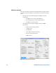
There are two presets, which can be selected using the “Preset...”
button. Trying both can be helpful for debugging. The “Optimized
Parameters” is used as default, since it works with most DUT. The
“CTS Parameters” represents the link training procedure
recommended by the CTS; however, this link training procedure
might not work with every DUT.
The option “Encoded Lane Number” option (in the main window)
allows to define the lane number which is encoded in the training
Pattern. By default, this value is always set to “Lane 0”. When you
want to run link training on another physical port of the DUT, just
connect that port to the J-BERT; the lane number can remain “Lane
0”. However, some DUTs require the lane number being set to the
corresponding physical port number.
The option “Encoded DUT TX Preset Hint” allows to define the
equalization preset that is requested for the DUT.
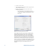
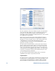
Loopback Pattern
The pattern which is continuously transmitted in loopback mode can
be defined in the “Loopback Pattern” box, as shown in Figure 9. You
can select between the PCI Express Compliance Pattern, the PCI
Express Modified Compliance Pattern, and a custom pattern file.
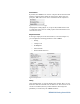
16 N5990A-301 Getting Started Guide
Figure 8: Sequence to Loopback Mode