
Technical data

Note that some jitter/SSC parameters will reset the sequencer when
modified. This means that the current sequencer state is left and the
link training is restarted. With the default settings, this means you'll
have to click the “Manual Trigger” button again to start link training.
The PCIe Link Training Suite tries to minimize the sequencer resets
as much as possible, but it is recommended to keep an eye on the
sequencer state when changing jitter or SSC parameters.
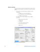
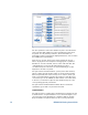
Interferences
Click the "Interferences…" button to open the interferences window.
You can modify the common-mode and differential-mode sinusoidal
interferences.
If you are connected to an 81150A AWG, common-mode interference
is generated using this AWG. If there is no AWG connected, common-
mode interference is generated with the J-BERT J20 module. Using
the J20 is less accurate and cannot be combined with differential-
mode interference. Be sure to have the AWG/J20 connected properly.
If you use calibration data, the compliance interference values will
use calibrated levels.
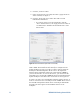
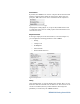
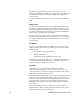
Bit Error Rate Measurement
You can click the "Start BER Measurement" (Figure 13) in the right
part of the window to automatically poll the J-BERT's bit and error
counters. By default, the displayed BER (Bit Error Rate) is calculated
from the total number of bits and total number of errors. You can
click the button on the left side of the BER display to toggle to the
current BER, which is the calculated BER of the last error counter
reading. Note that neither of these number is necessarily always
equal to the BER displayed in the J-BERT, since the measurement
intervals might be different.
You can click "Reset BER Measurement" to reset the bit- and error-
counter.
The BER can be used to determine whether link training was
successful or not. A very high BER and increasing error count could
indicate that no link training was performed, because the error
counter is always programmed to only compare the loopback pattern.
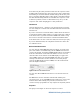
Sequencer
The group box in Figure 14 shows the sequencer control.
20 N5990A-301 Getting Started Guide
Figure 13: Bit Error Rate Measurements