
Keysigth Technologies N4903B J-BERT


dataTec ▪ Ferdinand-Lassalle-Str. 52 ▪ 72770 Reutlingen ▪ Tel. 07121 / 51 50 50 ▪ Fax 07121 / 51 50 10 ▪ info@datatec.de ▪ www.datatec.de
21
21 | Keysight | J-BERT N4903B High-Performance Serial BERT, 7 Gb/s and 12.5 Gb/s - Data Sheet
Error Detector Specications continued
Auxiliary output AX T
This output can be used to provide either cloc or data signals
loc cloc signals from the input or the recovered cloc signals
in DR mode.
Data weighted and sampled data.
Amplitude 600 mV typical
Interface C coupled, 50 Ω noinal
Connector SMA female
Pattern capture
The error detector can capture up to 32 MB data bits from the
device under test. The captured data bits are displayed in the
pattern editor in hex or binary format. The data bits can be used
as expected data for BER testing or can be saved for post
processing.
SER/ER Analysis ption A02
The symbol error ratio (SER) analysis allows error counting of
coded pacetized and retimed data streams. SATA and SB3 are
popular examples of serial bus standards using retimed loopbac
mode for receiver tolerance testing. SER analysis includes the
automatic handling of the running disparity of 8B/10B coded
patterns ltering of up to 4 user-denable ller symbols ltering
without any dead times up to 11.5 Gb/s (up to 12.5 Gb/s when
using analyzer with external cloc display of the error ratio as
SER or calculated BER. This reuires S rev. 6.6 or later. rame
error ratio ER analysis reuires S rev. 6.8 or later. or PIe
3.0 the option A02 enables the error counter to ignore changes
in length of 128 bit/130 bit coded Sip rdered Sets. To use this
functionality N4903B Software revision 7.40 or higher is reuired.
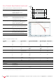
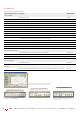
igure 28. Burst mode allows recirculation loop testing
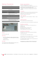
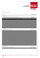
igure 29. The analyzer options A02 and A03 enable error counting of devices such
as PIe SATA SB3.0 and SB3.1 that use retimed and coded loopbac
Checked data
Backlash
CDR
settling
time
Sync. time
Burst
High
Low
Gate input
Data input
Table 27. Specications for the auxiliary output
Gating input GATE IN
If a logical high is applied to the gating input the analyzer will
ignore the incoming bits during a BER measurement. The ignored
bit seuence is a multiple of 512 bits. or measuring data in
bursts of bits, rather than a continuous stream of bits, a special
operating mode is used. This is the burst sync mode. In this case
the signal at the gating input controls the synchronization and the
error counting for each burst.
This is an important feature for recirculation loop measurements.
If cloc data recovery DR is used to recover the cloc from the
burst data the DR taes 2 s from the start of the burst data
to settle. The number of bits needed to synchronize itself during
a burst depends on whether the pattern consists of hardware
based PRBS data or memory based data. To run properly in burst
mode the system needs a baclash of data after the gating input
returns to high. During each burst, the gating input has to remain
passive.
Burst synchronization time 1536 bits for PRBS
15 kbit for pattern
Backlash 1536 bits in non-CDR mode
1.5 µs in CDR-mode
Gate passive time 2560 bits in non-CDR mode 2560 bits or
1.5 µs whichever is longer, in CDR mode
Interface levels TTL levels
Pulse width 256 clock periods
Connector SMA female
Table 28. Specications for gating input
Analysis of 128b/132b coded patterns ption
A03
The analysis of 128b/132b coded patterns enables receiver
testing of SB 3.1 ports. The BERT error detector ignores the
128b/132b coded Sip rdered Sets during error counting. It is
able to handle the variable length of these SP S. The max. bit
rate for this mode is 10.35 Gb/s. To use option A03 functionality
the N4903B software revision 7.60 or later is reuired.