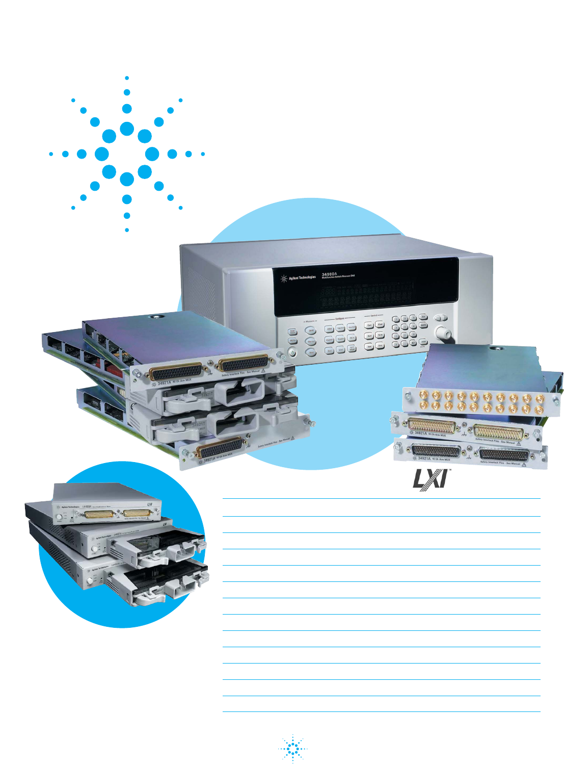
Agilent 34980A and L4445A Configuring an RF/Microwave Switch System Application Note 34980A and Plug-in Modules Contents L4400 Modules Introduction 2 Overview of 34980A RF/Microwave Switch Modules 3 Overview of 34945A/L4445A RF/Microwave Switch/Attenuator Driver 5 Key RF/Microwave Test System Specifications 7 Tips in building an RF/Microwave Test System 9 Key factors in selecting RF/Microwave Switches 10 Controlling Agilent Switches/Attenuators 11 34945EXT Distribution Board Configuration
Introduction LAN (Ethernet) is fast becoming the basis for a new set of instrumentation called LXI, or LAN eXentions for Instrumentation. LXI is a collection of standards that specify how instruments behave on LAN. The 34980A Switch/Measure Unit and the L4400 Modules are both LXI Class C compliant which means these instruments can be operated via LAN, follow a specified LAN protocol, and adhere to requirements such as a built-in Web Server, IVI software drivers, and others.
However, you may need to rapidly deploy custom RF/Microwave Switch solutions for your testing needs, so you need to be in control of lead times and costs associated with those switch solutions. In other words, you are a Do-It-Yourselfer. This application note will focus mainly on helping the Do-It-Yourself engineer who needs to control discrete external switches/attenuators.
Using RF and Microwave Modules Using 34980A mainframe modules to construct your high frequency test system has the following attributes: Benefits: • Convenient – no special hardware mounting • Easy re-configuration using flexible cables • Easy to add switches by adding switch modules • Easy to replace switches by replacing switch modules Limitations: • Longer signal paths between DUT and instruments • Higher insertion loss with longer, flexible cables • Low-loss flexible cables are very expensive • Signal p
34945A Plug-in Module Overview of 34945A/L4445 RF/Microwave/Attenuator Driver The 34945A/L4445A Microwave Switch/Attenuator driver is designed to support virtually any RF/Microwave switch or attenuator. The two products make it especially easy to control and monitor Agilent’s most popular RF/Microwave switches and attenuators.
The previous figure shows some key aspects of the 34945A/L4445A Switch Driver: • Each 34945A/L4445A module can supply 24 V to the first 34945EXT • Daisy chained 34945EXT’s must use an external power supply • Each 34945EXT can only support one voltage type (24 V, 12 V, or 5 V) • A total of eight (8) 34945EXT’s can be present in a single 34980A mainframe or connected to an L4445A Module • The 34945EXT’s can be daisy chained or directly connected to 34945A/L4445A modules There are five distribution boards (Y1
A disadvantage of continuous drive switches is they may change performance due to power dissipation in the switch housing. This can lead to deviations in performance of your test system. Each 34945EXT can drive a total of 2 A continuously when using an external power supply. When using an L4445A or 34945A mainframe module to supply power to the 34945EXT, the power from any particular slot in the mainframe is limited to 24 volts at 100 mA continuous + 200 mA pulse for up to 15 ms (25% duty cycle).
Frequency range The top frequency limits of switches are set by the size of the coaxial structure and connectors. SMA connectors operate from DC to 20 GHz. SMB connectors operate from DC to 4 GHz. Switch specifications such as Insertion Loss, Isolation, and VSWR degrade with increasing frequency operation. Insertion loss Insertion loss is a measure of signal loss in the switch or signal path (in dB).
Termination At high frequencies, all signals must be properly terminated. With improper termination (open end or mismatched impedance), signals can be reflected from the termination point back towards the source. This will result in an elevated VSWR and can even damage the signal source. Coaxial cables come is various characteristic impedances (typically 50 or 75 ohms), and the cable needs to be terminated in the same impedance. Termination usually takes place at the measurement instrument or DUT.
6. Choose a switching sub-system that is easy to configure, verify, and provides the capacity to expand your test system in the future. How you control external switches is a key factor, since you may require position indication that gives the actual state of the switch (vs. the programmed state of the switch). 7. Once your system is assembled, make detailed measurements with the DUT in place for every path and understand such performance factors as impedance matching, phase delay, and insertion loss. 8.
A test system with many Failsafe-type switches requires a significant amount of current to maintain switch closures. Some RF /Microwave Switch Drivers can actually drive over 20 A of current to control these types of switches. They require a high-current power supply and the routing of relatively high-gage wires to and from the driver module, power supply, and switch. Switch manufacturers provide latching-relay switches that only require a 10-20 ms pulse of current to change the state of the switch.
Position feedback is often a standard feature with Agilent switches, because the construction of the switch drive signals can also feed back informationabout the state of the switch. D-sub socket connectors allow for the easiest connection to Y115x distribution boards. There are other options than can be purchased or specified for switches/attenuators. Here are a few that are worthy of comment: • TTL/CMOS drive • Solder lugs • Current interrupts The 34945EXT can drive switches with TTL/CMOS control signals.
Headers for driving LEDs Y1153A P111 P110 LED2 LED1 84904/5/8 ATT2 USE ONLY ONE P102 P101 ATT1 USE ONLY ONE 84904/5/8 4 3 T +V A T A T 1. First, find the Agilent switch or attenuator required along the leftmost columns in Table 1 and Table 2. Adjacent columns show the recommended options for the relays. If these relays and options are ordered, cable construction, indicator read back and power becomes very simple.
Table 1.
Table 1.
Table 2.
Tables 1-7 will describe which kits are appropriate for the various switches and attenuators.
Table 3. The Y1150A Distribution Board Y1150A Switch options Coil voltage (24 V) 124 Position feedback 402 Connector type (9-pin) 201 Switch types: N1810UL, N1810TL, N1811TL, N1812UL Cable: 9-pin to 10-pin These are latching relays, so each switch uses two of the 16 coil drivers available through the distribution board. Therefore, eight switches can be controlled by this board. 34945EXT channels are paired to drive dual relays: 1:11, 2:12, 3:13, etc. Switches are driven with a 15 ms pulsed voltage.
Table 4. The Y1151A Distribution Board Y1151A Switch options Coil voltage (24 V) 024 Position feedback Comes Standard Connector type (16-pin) 161 Switch types: 87104, 87106, 87406, L7104, L7106, L7204, L7206 Cable: 16-pin to 16-pin Each multi-port switch requires up to eight coil drivers, so this board can drive two such switches. LED’s work from left to right with each representing a particular port of the switch. This switch comes standard with position feedback.
Table 5. The Y1152A Distribution Board Y1152A Switch options Coil voltage (24 V) Comes Standard Position feedback Comes Standard Connector type (16-pin) 161 Switch types: 87204, 87206, 87606, N181x (see Y1150A) Cable: 16-pin to 16-pin and 9-pin to 10-pin This board is a hybrid that can drive different types of switches. A 6-port switch requires twelve coil drivers. With four coil drivers remaining available, two N181x switches can be added. This is actually a fairly common situation.
Table 6. The Y1153A Distribution Board Y1153A.1 Switch options Coil voltage (24 V) 024 Position feedback Comes Standard Connector type (10-pin) Comes Standard Switch types: 84904, 84905, 84906, 84907, 84908 Cable: 10-pin to 10-pin Y1153A.
The Agilent 8494/5/6 attenuators come standard with a Viking connector and a Viking to bare wire cable. The Agilent 8490x attenuators use a 10-pin socket header. Both are supported on the Y1153A. The As and Ts are nomenclature that represent Attenuator or passthrough, so the attenuator section is either inline or bypassed. Position feedback is cleverly combined with the drive lines to indicate which section has been selected. That is reflected in the LEDs which represent the selected sections.
Table 7. The Y1154A Distribution Board Y1154A Switch options Coil voltage (24 V) Comes Standard Position feedback Comes Standard Connector type (10-pin) 161 Switch types: 87222, N181x (see Y1150A), L7222C Cable: 10-pin to 14-pin and 9-pin to 10-pin This board is a hybrid since it supports two different types of switches. Most test systems rarely need more than two Agilent 87222 transfer switches. The Agilent 87222 transfer switches only use two coil drivers each, so twelve coil drivers remain available.
Y1155A Y1155A P111 P110 LED2 LED1 DRIVE PWR POS IND 18 17 16 15 14 13 12 11 +VI GND +VR +VR 18 17 16 15 14 13 12 11 J106 J105 J104 8 7 6 5 4 • Position Indicators (Open collector or TTL/CMOS Digital Input) 3 • Coil Drive (Higher current Digital Output – pulsed or continuous) 2 There are three main sections: 1 +VI +VR GND 8 +VR 7 6 5 4 3 2 1 Custom Switching and the 34945A/L4445A Switch Driver The Y1150A through Y1154A provide very specific solutions for co
The 34945EXT only supports Common Positive coil drive, so you must connect the common connection on the switch to the +VR lines on the Y1155A, and the switch must use Common Positive drive circuits. Position Indicators These are just Digital Inputs that respond to the same voltage level as the coil drive or TTL signals. The 34945EXT allows inverting the polarity of the position indicator input, so you can indicate the desired logic level.
Example 34945A/L4445A Switch Driver Configurations The following two examples should give you a pretty good idea of how to configure a typical RF/Microwave Switch system based upon the Agilent 34980A and 34945A/ L4445A Switch Driver. Example #1: A test system is being built that requires the following Microwave Switching: • (4) DC-18 GHz SP6T Switches • (7) DC-18 GHz SPDT Switches We will choose switches that are latching, use 24 V coils, have position feedback, and socket connectors, where possible.
Here is a possible Agilent 34980A configuration with discussion points: • 34980A Switch/ Measure Unit • (1) 34945A Switch/ Attenuator Driver w/cable • (3) 34945EXT with RJ-45 extender cables • (3) Y1154A Distribution Boards • (3) Y1155A Distribution Boards • (3) Y1153A Distribution Boards • (5) Y1158A Cable Kits for 87222E switches and 84905M attenuators • Optional (6) Y1159A Cable Kits for LEDs If using the L4445A Switch/Attenuator, simply replace 34980A, 34945A, and one of the 34945EXT’s above with a sing
The Web Server Diagnostic Tool The 34980A/L4445A has a built-in Web Server that provides a very powerful configuration, diagnosis, and verification tool. All you need is a LAN connection, Web Browser, and the IP address. If your computer can access eBay.com, you can access a 34980A or L4445A module, from anywhere. You need NO other software to completely configure the 34980A/L4445A. All module drivers exist within the 34980A/L4445A.
When developing test system programs, you can open up a Web Browser to the 34980A/ L4445A, and you can observe switches closing and configurations changing. The Web Server can be set to capture every command/response coming from any interface: Web Browser, USB (34980A only), GPIB, or LAN. The Web Browser is included in this list because it actually sends programming commands (SCPI) to cause changes to the instrument. This helps with understanding the sequence of your test program.
A switch executive is an external software package that provides the following features: • Switch management and report generation • Creating switch paths callable from any test program • Simplify configuration of switching paths • Mutual exclusion between channels avoids unwanted collisions • Graphical end-to-end routing between test points • Typically works through IVI driver supplied by instrument vendor The 34980A/L4445A provides the critical parts of this functionality related to switching, and it prov
Conclusion You have been introduced to a number of 34980A/L4445A capabilities related to RF/Microwave switching. You have gained a better understanding of how an RF/Microwave test system might be built using the 34945A/L4445A Switch Driver to control discrete switches and attenuators.
Agilent Email Updates www.agilent.com/find/emailupdates Get the latest information on the products and applications you select. Agilent Direct www.agilent.com/find/agilentdirect Quickly choose and use your test equipment solutions with confidence. Agilent Open www.agilent.com/find/open Agilent Open simplifies the process of connecting and programming test systems to help engineers design, validate and manufacture electronic products.