
Technical data
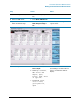
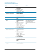
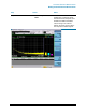
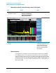
Table Of Contents
- EMC Measurement Application Measurement Guide
- Table of Contents
- 1 EMC Measurements
- 2 Conducted Emissions Measurements
- 3 Radiated Emissions Measurements
- A: Line Impedance Stabilization Networks (LISN)
- B: Antenna Factors
- C: Basic Electrical Relationships
- D: Detectors Used in EMI Measurements
- Glossary of Acronyms and Definitions
11
Conducted Emissions Measurements
Making Conducted Emission Measurements
2 Turn on the signal analyzer. a. Press the front-panel power
key.
3 Select the EMC mode. a. Press Mode, EMI Receiver.
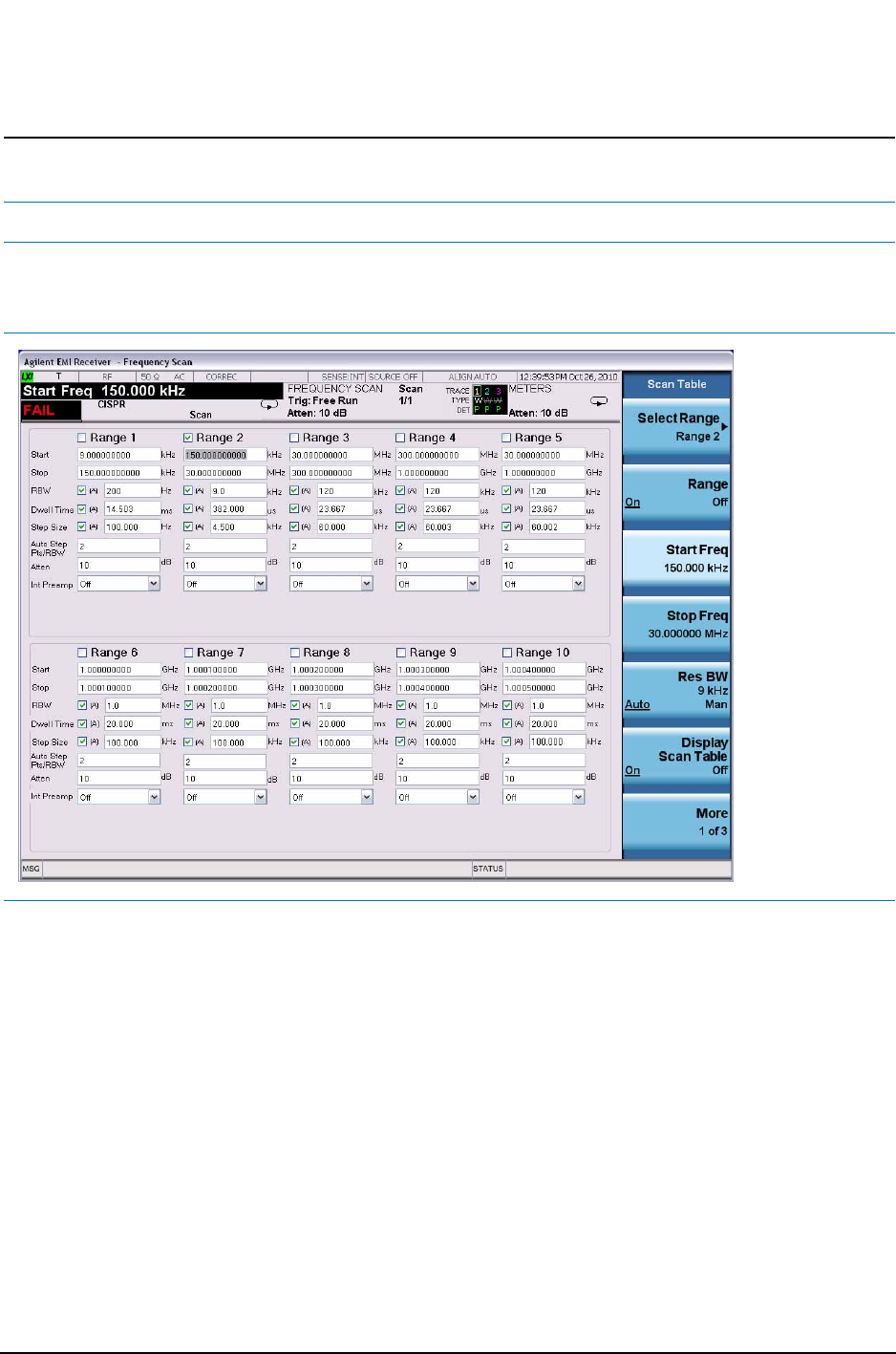
4 Open the scan table and
select the desired range
a. Press Meas Setup, Scan
Tabl e, Range 2, Range to
On.
Deselect any other range that has
a green check.
5 Load Quasi-peak limit line a. Press Recall, Data, Limit
Lines 1, Open.
b. Select My Documents,
EMC limits and
Ampcor, Open,
Limits, Open, Files
of type.lim,
c. Scroll to EN 55022,
Class A Cond,
Quasi-peak.lim,
Open.
The limit line will be turned on
after loading, If no data exists for
Trace 1, the Limit Line will not
display.
Step Action Notes