Agilent N2610A FrameScope 350 Network Performance Analyzer User’s Manual Version 3.
Notices © 2002 Agilent Technologies, Inc. Manual Part Number No part of this manual may be reproduced in any form or by any means (including electronic storage and retrieval or translation into a foreign language) without prior agreement and written consent from Agilent Technologies, Inc. as governed by United States and international copyright laws. N2610-90000 Edition First edition, July 2002 Agilent Technologies, Inc.
In This Guide… This user’s guide contains information for using your FrameScope 350 handheld network performance analyzer using software version 3.0.2. Note that some systems running earlier software may not provide all of the features described in this manual; systems running later versions of software may operate differently than described in this manual. Be sure to refer to any user’s manual supplements or release notes that came with the unit or call 800-452-4844.
iv Agilent FrameScope 350 User’s Manual
Contents 1 Introducing the FrameScope 350 The FrameScope 350 at a Glance 2 The DualRemote 350 at a Glance 6 The Main Menu at a Glance Getting Started 2 7 10 Network Testing with the FrameScope 350 Network Testing Overview Examining the Network Running an Autotest 16 17 19 Changing the Autotest Metrics Using the Stations List 24 Performing a Ping Test 28 Performing a Trace Route 31 Performing SNMP Queries Viewing Statistics 23 34 37 Generating Network Traffic 40 Performing a MAC Loopb
Using CompactFlash™ Cards Printing Labels 4 90 Fiber Testing Fiber Testing Overview 94 Calibrating the Tester 96 Setting Up an Autotest 101 Running an Autotest 5 88 114 Cable Testing in Expert Mode Testing Overview 117 Changing to Expert Mode 118 The Expert Autotest Setup The Expert Tools Menu 119 134 Running COAX and TWINAX Autotests 6 Expert Fiber Testing About Fiber Expert Mode 146 Changing to Expert Mode 147 Viewing Probe Information The Fiber Tools Menu 7 148 150 System Op
Printer Setup 169 Network Settings Remote Control 173 SNMP Settings 174 Demo Mode 8 170 175 Network Performance Analyzer Reference Network Connection Network Database 179 181 Network Performance Autotest Statistics 202 Network Tools 205 Remote Control 209 Memory Requirements 9 Calibration 212 216 Memory Requirements 220 Specifications Physical 224 Environmental Electrical Ports Display 225 226 227 229 Fiber SmartProbe+ 12 218 DualRemote 350 Reference The DualRemote 350 11
viii Agilent FrameScope 350 User’s Manual
Agilent N2610A FrameScope 350 Network Performance Analyzer User’s Manual 1 Introducing the FrameScope 350 The FrameScope 350 at a Glance 2 Front View 2 Side Views 3 Controls 4 Ports 4 The DualRemote 350 at a Glance 6 The Main Menu at a Glance 7 The Network Tab 8 The Cable Tab 9 Getting Started 10 Switching the FrameScope On and Off 10 Checking Power and Charging the Battery 11 Connecting to the Network 12 Using the FrameScope 350 13 Running a Test 13 The Agilent FrameScope 350 Network Performance Analyzer
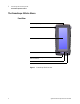
1 Introducing the FrameScope 350 The FrameScope 350 at a Glance The FrameScope 350 at a Glance Front View SmartProbe port (top) Strap cleat Color touch screen Power button CompactFlash™ memory card slot (bottom) OK button Scroll button Figure 1 2 FrameScope 350 Front View Agilent FrameScope 350 User’s Manual
Introducing the FrameScope 350 1 The FrameScope 350 at a Glance Side Views Stylus clip USB ports DC Power input Battery pack (back) Figure 2 Left Side Headset port Serial port Flip-out stand (back) Figure 3 Agilent FrameScope 350 User’s Manual Right Side 3
1 Introducing the FrameScope 350 The FrameScope 350 at a Glance Controls Color Touch Screen The FrameScope 350’s touch screen is the main user interface. Test controls and results are shown here. Simply press the screen with your finger or a stylus to navigate through the menus and test controls. Power Button Press the Power button briefly to switch the unit on. To switch the unit off, do one of the following: • Press Power twice. • Press Power once, wait 5 seconds and the unit powers off.
Introducing the FrameScope 350 1 The FrameScope 350 at a Glance Talkset Port This port allows you to connect Agilent’s FrameScope talkset (N2605A-137) for two-way voice communication between the FrameScope and DualRemote over copper cabling. DC Power Input The DC power input accepts any of the Agilent 12 Vdc power adapter/chargers. CAU T ION Agilent FrameScope 350 User’s Manual Use only the 12 Vdc adapter/charger supplied with your FrameScope 350.
1 Introducing the FrameScope 350 The DualRemote 350 at a Glance The DualRemote 350 at a Glance Pair status indicators Warning indicators Test progress and Result indicators Fault location indicators Diagnostic indicators Power indicator Power button OK button Scroll button Figure 4 DualRemote Front View The Agilent DualRemote 350 is used with the FrameScope 350 when performing cable testing. The DualRemote is positioned at the far end of the cabling run being tested.
Introducing the FrameScope 350 1 The Main Menu at a Glance The Main Menu at a Glance Title bar Tab area Status display area Navigation buttons Figure 5 The Main Menu Title Bar Displays the name of the current screen. Tab Area Display the currently selected tab. The FrameScope 350 provides two tabs: Network and Cable. Select a tab to choose the type of testing you want to do.
1 Introducing the FrameScope 350 The Main Menu at a Glance The Network Tab Tab title Network resources area Error Flag Utilization graph System menu button Tools menu button Autotest button Figure 6 FrameScope Network Tab Tab Title Displays the name of the tab. Network Resource Area Shows all of the detected network resources. When you press the Network tab, the FrameScope performs auto discovery of network resources.
Introducing the FrameScope 350 1 The Main Menu at a Glance Autotest Button Calls the Network Autotest Setup screen. The Cable Tab Tab title Certification test buttons Setup menu button Calibration button System menu button Figure 7 N O TE FrameScope Cable Tab (normal mode) The Cable tab will look different if Expert Mode is turned on. Tab Title Displays the name of the tab. Certification Test Buttons Launch a certification autotest.
1 Introducing the FrameScope 350 Getting Started Getting Started Switching the FrameScope On and Off 1 To switch the FrameScope on, briefly press the Power button on the front panel. The screen will light and a brief tone will sound. 2 While the unit is on, briefly pressing the Power button will call the Sleep/Shutdown window. • Press Sleep to put the unit in sleep mode. When the FrameScope is in sleep mode, briefly press the Power button or press the screen to reactivate it.
1 Introducing the FrameScope 350 Getting Started Checking Power and Charging the Battery The FrameScope’s battery should provide enough power for a typical day of testing. The AC power adapter/charger can also be used to power the unit and to recharge the battery. To check the battery’s charge level, perform these steps: 1 Switch on the FrameScope, if necessary, by pressing the Power button on the front of the unit. 2 Observe the battery icon in the Status display area on the Main Menu.
1 Introducing the FrameScope 350 Getting Started Connecting to the Network The FrameScope 350 uses test probes to connect to the network you are testing. Follow these steps to connect your unit to the network: 1 Select an appropriate Agilent test probe for your application: • Select a Channel SmartProbe for testing twisted pair using patch cords. • Select a Link SmartProbe for testing twisted pair at network outlets. See also “Cable Testing Overview” on page 57.
1 Introducing the FrameScope 350 Getting Started Using the FrameScope 350 You operate the FrameScope using its front panel touchscreen and control buttons. When testing with the unit, use the following operating tips: • Select items on the display by pressing them with your finger or with a stylus or by scrolling the highlight bar with the scroll button. The touch screen may not detect a quick press; you should press firmly. • Many screens have lists of items that you can navigate using the Scroll button.
1 Introducing the FrameScope 350 Getting Started See “Viewing Details and Statistics” on page 26 for information on reviewing network test results. See “Viewing Result Details” on page 82 for information on reviewing cable test results.
Agilent N2610A FrameScope 350 Network Performance Analyzer User’s Manual 2 Network Testing with the FrameScope 350 Network Testing Overview 16 Examining the Network 17 Network Overview 17 Detailed List 18 Running an Autotest 19 Changing the Autotest Metrics 23 Using the Stations List 24 Viewing Details and Statistics 26 Performing a Ping Test 28 Performing a Trace Route 31 Performing SNMP Queries 34 Viewing Statistics 37 Generating Network Traffic 40 Performing a MAC Loopback 43 Locating a Hub Port with Bl
2 Network Testing with the FrameScope 350 Network Testing Overview Network Testing Overview The following steps describe the general procedure for performing network analysis testing using the FrameScope 350. 1 Power the unit on. See “Switching the FrameScope On and Off” on page 10. 2 Press the Network tab on the Main Menu to begin. 3 Connect to the network under test. See “Connecting to the Network” on page 12. The FrameScope automatically begins to poll the network and locate devices.
Network Testing with the FrameScope 350 2 Examining the Network Examining the Network Network Overview • Press the Network tab on the Main Menu to begin the FrameScope auto discovery on your network. The Network resources area of the display will show a list of detected network devices.
2 Network Testing with the FrameScope 350 Examining the Network Detailed List 1 To view a detailed list of network resources, press on any category in the Network Resources area. A triangle indicates that a list is available for that category. Press icon to view details 2 Use the Scroll button to select items in the list. The Collapse List and Expand List button is renamed View when the highlight is on a particular station. Press the View button to see details of the selected item.
Network Testing with the FrameScope 350 2 Running an Autotest Running an Autotest This section describes how to run an Autotest on the network using the FrameScope 350. The FrameScope can store Autotest suites that define which network elements to test. 1 From the Network Overview screen (see page 17) press the Autotest button. The Network Autotest Setup screen is displayed.
2 Network Testing with the FrameScope 350 Running an Autotest 2 If you want to save this Autotest suite, or load a previously-stored suite, press the Suite button. 3 Select a stored suite from the list or select Create New, then press the Next button. You can select if you want to reload the default suite. 4 If you Create New, you will be prompted to enter a new name.
2 Network Testing with the FrameScope 350 Running an Autotest 5 On the Network Autotest Setup window, press the Iterations button to select how many times the test is to be run. 6 Enter the number of times you want the test to run in the number entry box. 7 Enter the time in minutes to wait between tests in the Interval text box. 8 When you have finished press OK. 9 On the Network Autotest Setup screen, use the Delete and Add buttons to remove or insert elements from the resources list.
2 Network Testing with the FrameScope 350 Running an Autotest 11 When you have finished setting up the test, press the Start Test button (or press OK) on the Network Autotest Setup screen. The test will begin. 12 To stop the test at any time press the Stop Test button. 13 To view information about a network element’s results, select the element from the list and press the Details button. 14 Press the Save Results button to store the test data on the CompactFlash™ card.
Network Testing with the FrameScope 350 2 Changing the Autotest Metrics Changing the Autotest Metrics The FrameScope 350 provides a measure of service speed and efficiency by emulating a client device in the network. By making a request for service to a key device, and comparing the results to reasonable expectations, it provides a rating of the service. However, the default numbers used to determine the rating may not apply to the network under test.
2 Network Testing with the FrameScope 350 Using the Stations List Using the Stations List When a network resource on the Network tab is shown with a black triangle, you can press the resource to display the Network Database screen, which includes the Stations List. 1 On the Network tab, press the resource you wish to view. Press here to view details Stations List 2 Use the Scroll button to navigate through the items on the Station List.
Network Testing with the FrameScope 350 2 Using the Stations List 4 You can use the Settings button to reorder the Station List and select what information is displayed. 5 You can use the Database Tools button to update, erase, load or save the Stations List or delete a resource from the Stations List.
2 Network Testing with the FrameScope 350 Using the Stations List Viewing Details and Statistics 1 Select a station on the Station List and then press the View button. 2 Press the Statistics button to view statistics about the station.
2 Network Testing with the FrameScope 350 Using the Stations List 3 On the Station Detail screen, press Tools to see a list of test tools that can be used on the selected station. These tools are describe in more detail in the following sections. N O TE Agilent FrameScope 350 User’s Manual The tools that are displayed on the Station Tools list will vary depending on what type of station you are viewing. Not all tools are available for every type of station.
2 Network Testing with the FrameScope 350 Performing a Ping Test Performing a Ping Test The Ping test allows you to check if communications can be established with a particular remote node. The FrameScope “pings” a remote node by sending it a request message. If the remote device is active and reachable it will respond. Follow these steps to run a Ping test.
2 Network Testing with the FrameScope 350 Performing a Ping Test 2 Press the Ping button to call the Ping screen. 3 Enter the device you want to ping in the Target box. You can enter the device name or address. 4 Select the ping options you want, selecting IP or IPX, length of the ping, and the number of iterations. 5 Enter the Time To Live and whether you want fragmentation in the IP Options area. Or if you selected IPX above, select the IPX request type: Diagnostic or PING.
2 Network Testing with the FrameScope 350 Performing a Ping Test 7 Observe the results of the Ping test. The screen will show the frame length you selected, the number of requests (pings) sent and the number of replies received. Data on the response times are also displayed. 8 To run the test again press the Start button.
Network Testing with the FrameScope 350 2 Performing a Trace Route Performing a Trace Route The Trace Route test allows you to determine the path through the network to a particular device. The FrameScope sends data packets over the network and returns the routers on the path and the time it took for each hop. The following procedure describes how to run a Trace Route test.
2 Network Testing with the FrameScope 350 Performing a Trace Route 2 Press the TraceRoute button to call the TraceRoute screen. 3 Enter the device to which you want to trace in the Target box. You can enter the device name or address. 4 Select the maximum number of hops to be reported. 5 Press the Start button to begin the TraceRoute test. The TraceRoute Results screen will be displayed.
Network Testing with the FrameScope 350 2 Performing a Trace Route 6 Observe the results of the TraceRoute test. The screen will show the number and address of each hop. In addition the delay (in seconds) to each hop is shown. The delay is cumulative, but since each termination is measured individually, an anomaly may exist where an intermediate time is greater than a subsequent time due to network performance. 7 To run the test again press the Start button.
2 Network Testing with the FrameScope 350 Performing SNMP Queries Performing SNMP Queries The simple network management protocol (SNMP) query tool allows you to send a query to the management information database (MIB) and retrieve the available information for that host. The following procedure describes how to run an SNMP Query using the FrameScope 350.
Network Testing with the FrameScope 350 2 Performing SNMP Queries 2 Press the SNMP Queries button to call the SNMP Query screen. 3 Enter the device to which you want to query in the Target box. You can enter the device name or address. 4 The SNMP Settings button allows you to add SNMP communities and ports to the default “public” community and default port 161 or to change those set up for auto discovery. 5 Press the Start button to begin the SNMP Query test.
2 Network Testing with the FrameScope 350 Performing SNMP Queries 6 Observe the returned information on the SNMP Queries results screen. The screen will show the description, ID, and other information as returned by the remote host. 7 To run the test again press the Start button.
Network Testing with the FrameScope 350 2 Viewing Statistics Viewing Statistics You can use the FrameScope to view a variety network parameters, and see performance statistics for them. The following procedure describes how to use the FrameScope’s Statistics tool. 1 Press the Tools button on the main Network tab to display the Tools menu.
2 Network Testing with the FrameScope 350 Viewing Statistics 2 Press the Statistics button to call the Statistics screen. The screen shows network utilization and other traffic data such as frame counters, and protocol counters. 3 To view additional details, press any item shown with a black triangle.
2 Network Testing with the FrameScope 350 Viewing Statistics 4 For example, press Utilization on the Statistics screen to view the top talkers (most active devices) on the network. Press here to view details 5 Use the other buttons on the Statistics screen to switch between counts and percentages, protocols and frames, and so on. • Press Unicasts, Broadcasts, or Multicasts to view the top talkers for that frame type. • Press Errors to view a breakdown of the types of errors detected on the network.
2 Network Testing with the FrameScope 350 Generating Network Traffic Generating Network Traffic You can use the FrameScope’s Traffic Generator to create network traffic to stress the network and observe how is reacts under different loads. The following procedure describes how to use the Traffic Generator. 1 Press the Tools button on the main Network tab to display the Tools menu. 2 Press the Traffic Generator button. The Traffic Generator screen will be displayed.
2 Network Testing with the FrameScope 350 Generating Network Traffic 3 On the Parameters tab, configure the traffic characteristics as you desire. Press each parameter (Frame Length, Frame Rate, and so on) and enter the value you want in the on-screen keypad. See “Traffic Generation” on page 206. 4 To inject errors in the generated traffic, press the check box for the type of error you want (CRC, short frame, or long frame). See “Traffic Generation” on page 206.
2 Network Testing with the FrameScope 350 Generating Network Traffic 6 Press the box buttons to enter the Frame Type, MAC source, and MAC Destination. See “Traffic Generation” on page 206. Note that if you select an IP type frame, you will get additional selections for IP Source and IP Destination. 7 Press the Start button to begin generating traffic. The Traffic Generator activity screen is displayed. 8 Observe the traffic statistics.
2 Network Testing with the FrameScope 350 Performing a MAC Loopback Performing a MAC Loopback N O TE This procedure requires two FrameScope 350s; one at each end of the network circuit to be tested. You can perform a ping-like test on the media access control (MAC) layer (Layer 2). Using two FrameScopes, you can get results on the round-trip performance. 1 Connect two FrameScopes to the network. Connect one at each end of the network circuit you want to test. See “Connecting to the Network” on page 12.
2 Network Testing with the FrameScope 350 Performing a MAC Loopback 4 Press Start or press the OK button to begin the test. The FrameScope will search out the other FrameScope on the network and then report back the link results. 5 Review the transmission information on the MAC Loopback screen. 6 Press Start to repeat the test.
2 Network Testing with the FrameScope 350 Locating a Hub Port with Blink Port Locating a Hub Port with Blink Port You can use the FrameScope to locate a network connection’s port on a hub or switch. The FrameScope will toggle the port’s link indicator on and off causing it to blink. This section describes how to use the Blink Port feature of the FrameScope 350. 1 Connect the FrameScope to the remote end of the circuit whose hub you want to locate.
2 Network Testing with the FrameScope 350 Locating a Hub Port with Blink Port 4 To begin blinking the port, press the Start button. 5 Observe the hub or switch and note which port’s link indicator is blinking. That will be the port for the tested circuit. 6 To stop the blink, press the Stop button on the Blink Port screen.
Network Testing with the FrameScope 350 2 Viewing the Error Log Viewing the Error Log This section describes how to view the FrameScope’s error log. The error log tracks and displays any network problems that detected by the FrameScope 350. 1 From the main Network tab, press the Tools button to display the Tools menu.
2 Network Testing with the FrameScope 350 Viewing the Error Log 2 Press the Error Log button to call the Error Log screen. 3 Observe the errors listed in the log. 4 Press the Show All button to expand the error list and view all errors that were previously acknowledged by using the Ack button. 5 Press the Ack button to acknowledge the errors without clearing the log. 6 Press the Reset button to clear the log.
2 Network Testing with the FrameScope 350 Using the Test Database Using the Test Database The FrameScope 350 allows you to store (you must have a CompactFlash™ card installed) Autotest results for later review and downloading (see “Running an Autotest” on page 19, and step 14 on page 22). You can recall previously stored test data using the Tests Database tool. This section describes how to recall and delete stored tests. 1 Press the Tools button to call the Tools menu.
2 Network Testing with the FrameScope 350 Using the Network Database Using the Network Database The FrameScope 350 allows you to store (only on a CompactFlash™) network topologies for later review and downloading (see “Using the Stations List” on page 24). You can recall previously stored network data using the Network Database tool. This section describes how to recall and delete stored network data. 1 Press the Tools button on the Network Main Menu to call the Tools menu.
Network Testing with the FrameScope 350 2 Using the Network Database 6 To access the Database Tools menu press the Database Tools button. 7 To save the current network data, or to load previously stored network data, press the Load/Save Station List button. 8 Use the buttons on the Station List name screen to store the current network data, load stored data, or delete stored data. If you are storing data, you will be prompted to enter a name for the data file.
2 Network Testing with the FrameScope 350 Locating Switch Ports Locating Switch Ports The FrameScope 350 allows you to identify the switch ports being accessed by the FrameScope or any address on the network. This section describes how to create a list of switch ports being used. 1 Press the Tools button to call the Tools menu. 2 On the Tools menu, press the Locate Switch Port button to call the Locate Switch Port screen.
Network Testing with the FrameScope 350 2 Locating Switch Ports 4 The SNMP Settings button allows you to add SNMP communities and ports to the default “public” community and default port 161 or to change those set up for auto discovery. 5 Press Start to see the results of the Locate Switch Port. 6 Use the Scroll button to scroll through the list if necessary. N O TE The order of the information presented is not useful and should not be used in interpreting the list.
2 Network Testing with the FrameScope 350 Locating Switch Ports 54 Agilent FrameScope 350 User’s Manual
Agilent N2610A FrameScope 350 Network Performance Analyzer User’s Manual 3 Cable Testing with the FrameScope 350 Cable Testing Overview 57 Cable Testing Background 57 Cable Testing Procedure 59 Calibrating the Tester 61 Setting Up an Autotest 62 Opening the Setup Menu 62 Choosing the Profile 62 Choosing the Standard 62 Entering the Site Name 63 Choosing the Labeling Format 64 Choosing the Cable Type 71 Choosing the Connector Type 74 Choosing the Cable Pairing Convention 75 Entering the Operator Names 76 Ru
3 Cable Testing with the FrameScope 350 The cable test features of the FrameScope 350 allow you to easily certify new network installations for compliance with industry cable standards. N O TE 56 This chapter describes the standard FrameScope 350 cable test features. For information on using Expert Mode, see Chapter 5, “Cable Testing in Expert Mode”.
3 Cable Testing with the FrameScope 350 Cable Testing Overview Cable Testing Overview Cable Testing Background Industry standards for structured twisted-pair cabling require that both ends of each cabling run be tested to find the worst-case performance conditions. Therefore, certification testing requires a two-part test solution comprising a main unit and a remote unit with similar test capabilities.
3 Cable Testing with the FrameScope 350 Cable Testing Overview • The channel configuration provides a full end-to-end performance certification, including the cable run as well as the user’s patch cords at each end. The pass/fail limits for channel performance testing are less stringent than for link configurations to accommodate the performance degradation inherent in the two additional modular connections. The FrameScope and DualRemote use different test probes for link and channel tests.
3 Cable Testing with the FrameScope 350 Cable Testing Overview Structured Cabling Link Link Probe Link Probe Telecommunications Closet User Location Outlet FrameScope Figure 9 DualRemote Link Test Configuration Telecommunications Closet User Location Outlet User Patch Cord User Patch Cord Structured Cabling Link Channel Probe FrameScope Channel Probe DualRemote Figure 10 Channel Test Configuration Cable Testing Procedure The following steps describe the general procedure for performing cab
3 Cable Testing with the FrameScope 350 Cable Testing Overview 3 Switch on the FrameScope and DualRemote testers and connect them to the cabling to be tested. See “Connecting to the Network” on page 12. 4 Press the Cable tab on the FrameScope’s Main Menu screen and then press a test button to begin the test. You can run a preprogrammed autotest or configure your own test parameter values before running the test. • See “Choosing the Profile” on page 62. • See “Opening the Setup Menu” on page 62.
3 Cable Testing with the FrameScope 350 Calibrating the Tester Calibrating the Tester Before you begin a test, the FrameScope and DualRemote pair must be calibrated. Calibration allows the FrameScope to compensate for slight anomalies in its measurement hardware or that of the companion DualRemote unit. 1 Connect the FrameScope 350 and DualRemote 350 in either of the configurations shown below. &KDQQHO 3UREH /LQN 3UREH 3UHFLVLRQ &DOLEUDWLRQ &DEOH OR 2 On the main menu, press Calibration.
3 Cable Testing with the FrameScope 350 Setting Up an Autotest Setting Up an Autotest The tester must be configured for testing at each site by completing the following procedures. Opening the Setup Menu 1 On the Main Menu, press Setup. The Autotest Setup screen displays. Choosing the Profile The FrameScope 350 normally displays one or two limit options on the Main Menu, based upon the profile selected. If None is selected, then the two limit options are dependent upon the Standard selected.
Cable Testing with the FrameScope 350 3 Setting Up an Autotest 1RWH 7KH 3URILOH PXVW EH VHW WR 1RQH LQ RUGHU WR FKDQJH WKH 6WDQGDUG 1 On the Autotest Setup screen, press Standard, then Edit. The Standard Setup screen displays. 2 Select the desired standard, then press OK. The Autotest Setup screen will then show the selected standard. The selected standard is applied to all subsequent tests.
3 Cable Testing with the FrameScope 350 Setting Up an Autotest 2 Select Create a New Site Name, then press Next. (The OK button changes to a Next button when you select Create a New Site Name.) The screen changes, to allow naming the site. 1RWH 7R FKDQJH WKH QDPH RU ODEHOLQJ IRUPDW IRU DQ H[LVWLQJ VLWH SUHVV WKH VLWH QDPH RQ WKH OLVW WKHQ VHOHFW (GLW 9LHZ DQG SUHVV 1H[W 3 Press the icon under (QWHU 1HZ 6LWH 1DPH The onscreen keyboard opens.
Cable Testing with the FrameScope 350 3 Setting Up an Autotest 1 On the Site Setup screen, press the preferred labeling format, then press Next. Simple Label Format When you choose the Simple labeling format, the following screen displays: To configure the simple labeling format: 1 If you want the numbers on the labels to increase automatically with each new label and test, press Enable Auto-Increment so that a checkmark appears, as in the figure above.
3 Cable Testing with the FrameScope 350 Setting Up an Autotest 2 To set the beginning number to other than 1, press the Enter Start Value field. The onscreen keyboard opens. 3 Press the backspace arrow to erase the number in the display, then press the number keys to enter the new starting number. Press OK. The keyboard closes, and the new starting number appears in the Enter Start Value field. 4 To set the number of cable runs to label and test, press the Enter End Value field.
3 Cable Testing with the FrameScope 350 Setting Up an Autotest TIA-606-A Label Format When you choose the TIA-606-A labeling format and press Next, the following screen displays: There are three formatting options within the TIA-606-A standard: • Class 1 and Class 2 have fields for Floor, Telecom Room, Panel, and Position. • Class 3 has fields for Building, Floor, Telecom Room, Panel, and Position.
3 Cable Testing with the FrameScope 350 Setting Up an Autotest Auto-Increment settings for the field highlighted, and the start and end values for the field highlighted. 2 If you want the numbers for any field to increase automatically with each new label and test, highlight that field, then press Enable Auto-Increment so that a checkmark appears, as in the figure above. 3 To set the beginning number for a field to other than 1, highlight the category name, then press the Enter Start Value field.
Cable Testing with the FrameScope 350 3 Setting Up an Autotest 5 To set the number of instances of a category (for example, the number of floors), press the Enter End Value field. The onscreen keyboard opens. 6 Press the backspace arrow to erase the value in the display, then press the number or letter keys to enter the new value. Press OK. The keyboard closes, and the new ending value appears in the Enter End Value field. 7 Repeat steps 2 through 6 for all the selected categories. 8 Press OK.
3 Cable Testing with the FrameScope 350 Setting Up an Autotest Checkmarks indicate fields that appear in the labels. Yellow tags next to the categories indicate that automatic number incrementing is enabled for that field. To configure the hierarchical labeling format: 1 Press a category to check it for inclusion in the label, or to uncheck it so it does not appear. When all the desired categories are checked, press Next. The Site Setup screen changes to show the selected categories.
3 Cable Testing with the FrameScope 350 Setting Up an Autotest 4 Press the backspace arrow to erase the number in the display, then press the number or letter keys to enter the new starting value. Press OK. The keyboard closes, and the new starting value appears in the Enter Start Value field. 5 To set the number of instances of a category (for example, the number of floors), press the Enter End Value field. The onscreen keyboard opens.
3 Cable Testing with the FrameScope 350 Setting Up an Autotest 1 On the Autotest Setup screen, press the cable spool icon, then press Edit. The Cable Setup screen displays. 1RWH 7KH VFUROO EDU RQ WKH ULJKW RI WKH VFUHHQ VKRZV WKH ORFDWLRQ RI WKH GDWD VKRZQ DQG LV QRW D IXQFWLRQDO VFUROO EDU 7R VFUROO XVH WKH VFUROO EXWWRQ DW WKH ORZHU ULJKW RI WKH )UDPH6FRSH 2 Select the cable manufacturer, and press Next. The Cable Database screen displays. 3 Select a cable on the list, and press OK.
Cable Testing with the FrameScope 350 3 Setting Up an Autotest 4 Enter the pair count, cable construction, and impedance (default selections are available) and press Next. 5 Enter the nominal velocity of propagation (NVP) for each pair, if known, or select Calculate NVP from length. If you need to calculate the NVP from length, attach at least 50 feet of cable to the FrameScope with the far end disconnected, enter the measured length, and press Calculate.
3 Cable Testing with the FrameScope 350 Setting Up an Autotest Choosing the Connector Type Connectors from different manufacturers have different transmission characteristics. The FrameScope 350 compensates for those differences, if you tell it what connectors are used on the job. 1 On the Autotest Setup screen, press the connector icon, then press Edit. The Connector Setup screen displays.
3 Cable Testing with the FrameScope 350 Setting Up an Autotest 4 Select whether the connector is shielded or not and press Next. 5 Select the performance grade of the connector if known and press OK. The Autotest Setup screen displays, with the new connector type next to the connector icon. Choosing the Cable Pairing Convention To identify the correct pair in the test results, the FrameScope must be told what cable pairing convention is used.
3 Cable Testing with the FrameScope 350 Setting Up an Autotest Entering the Operator Names The names of the technicians performing the tests can be entered, and will appear on the test report. To enter the test technicians’ names: 1 On the Main Menu, press System. The System Settings screen displays. 2 Press Operators, then press Edit. The Operator Setup screen displays. 3 Choose the FrameScope unit’s testing location, either Telecom Room, Outlet, or Other. 4 Press the FrameScope Operator field.
3 Cable Testing with the FrameScope 350 Setting Up an Autotest entered names will appear with the keyboard and keypad buttons available. 5 Pick a name from the list or press the keyboard keys to enter the name of the technician using the FrameScope, then press OK. The keyboard closes, and the technician’s name appears in the FrameScope Operator field of the Operator Setup screen. 6 Choose the DualRemote unit’s testing location, either Telecom Room, Outlet, or Other. 7 Press the DualRemote Operator field.
3 Cable Testing with the FrameScope 350 Running an Autotest Running an Autotest To run an autotest: 1 If this is the first test of the day or after a long break, calibrate the tester. See “Calibrating the Tester” on page 61. 2 Connect the FrameScope 350 and Dual Remote 350 to the ends of the circuit needing certification. 3 On the FrameScope Main Menu, press the button identifying the selected test. The test executes.
Cable Testing with the FrameScope 350 3 Saving Test Results Saving Test Results Before saving test results, choose the storage site to save them to. 1RWH 7KH SURFHGXUHV EHORZ VKRZ VFUHHQV IURP WKH FRSSHU WHVWLQJ FRQILJXUDWLRQ 7KH SURFHGXUHV IRU ILEHU WHVWLQJ DUH HVVHQWLDOO\ WKH VDPH EXW WKH VFUHHQV PD\ GLIIHU LQ PLQRU GHWDLOV Choosing the Data Storage Location Test data can be saved to either the FrameScope’s internal memory or to an installed CompactFlash™ card.
3 Cable Testing with the FrameScope 350 Saving Test Results 2 On the System Settings screen, press Save To, then press Edit. The Storage Setup screen displays. 3 Select either Internal Flash or CFlash Card. 4 If you chose Internal Flash, press OK. The System Settings screen displays, with “Internal Flash” next to Save To. 5 If you chose CFlash Card, press Next. The Storage Setup screen displays a message about preparing the CompactFlash™ card.
Cable Testing with the FrameScope 350 3 Saving Test Results Saving the Results To save the test results for inclusion in certification reports: 1 After completing a test, press the Save button. The Save Results screen displays. 2 If the cable ID in the display is wrong, press the backspace arrow to erase it, and press the keyboard keys to enter the correct cable ID.
3 Cable Testing with the FrameScope 350 Viewing Result Details Viewing Result Details A Details button on Pass and Fail screens opens the Test Data screen. The Test Data screen lists the test parameters and indicates passing or failure for each. To view detailed test data for one of the test parameters: 1 Press the name of the test parameter. The Test Data screen displays buttons appropriate for the selected parameter.
3 Cable Testing with the FrameScope 350 Viewing Result Details 3 To view the Plots screen for the selected test parameter (if the Plots button is present), press Plots. The Plots screen displays. 4 To view the Locator screen for the selected test parameter (if the Locator button is present), press Locator. The Locator screen displays. Interpreting Test Results Detail Screens The various test detail screens present test data in different formats, as explained below.
3 Cable Testing with the FrameScope 350 Viewing Result Details Data Screens The Data screen shows detail of the selected test parameter results. The examples above show data of a passing test, at left, and a failing one, at right. The data included depends on which parameter is selected. (See steps 2, 3, and 4 of the “Viewing Result Details” on page 82.) The Data screens shown above include a table that displays details of the test results for two twisted pairs of copper cable.
3 Cable Testing with the FrameScope 350 Viewing Result Details boundary on passing test plots. On failing test plots, the Worst Margin button places the line at the frequency where the results exceed the acceptable limits the most. You can move the cursor around the plot screen by pressing the area you want to see and then using the scroll rocker to fine tune the location. The frequency of the cursor is displayed and the values in the table correspond to the cursor location.
3 Cable Testing with the FrameScope 350 Viewing Result Details the location using the scroll button to find the exact distance to that peak. By default, the distance shown is how far away the worst test result is from the closer of the FrameScope or DualRemote. To see the locator results for the different sets of twisted pair cables, press them on the list.
Cable Testing with the FrameScope 350 3 Using Talksets Using Talksets The 2-Way Talkset Kit (N2605A-137) allows operators at opposite ends of a copper cable run to coordinate their efforts. 1RWH 7KH WDONVHWV GR QRW ZRUN ZLWK RSWLFDO ILEHU FDEOLQJ To use talksets for communicating between the ends of a cable run: 1 Insert a talkset’s plug into the talkset jack on the FrameScope, and the plug of another talkset into the jack of the DualRemote. See “Talkset Port” on page 5, for the jack’s location.
3 Cable Testing with the FrameScope 350 Using CompactFlash™ Cards Using CompactFlash™ Cards The FrameScope 350 can use CompactFlash™ cards for storing large amounts of test data, for transferring data to a PC, and for installing new software. Installing CompactFlash™ Cards To install a CompactFlash™ card: 1 Find the CompactFlash™ card slot in the bottom of the FrameScope 350. See “CompactFlash™ Slot” on page 4, for the location of the slot. 2 Insert the CompactFlash™ card into the slot.
Cable Testing with the FrameScope 350 3 Using CompactFlash™ Cards 3 A screen describing the configuration procedure displays. The configuration executes in steps. 4 When the progress bar shows 100%, press OK. The FrameScope 350 will automatically change the Save to: setting on the System Settings to CFlash Card.
3 Cable Testing with the FrameScope 350 Printing Labels Printing Labels Printing Labels On Site The FrameScope 350 can print labels directly to a Brady TLS2200 label printer. The labeling parameters are set using the procedure “Choosing the Labeling Format” on page 64. When the FrameScope is configured as described in the following procedure, a label for the tested cable will be printed after saving a test result.
Cable Testing with the FrameScope 350 3 Printing Labels 3 Press Autoprint to enable the Autoprint function. A checkmark shows that the function is enabled. Press OK 4 Connect the N2605A-050 interface cable to the serial ports of the FrameScope 350 and Brady TLS2200. 5 Turn the Brady printer on. 6 Press the Func and Exit keys on the printer simultaneously. This sets the printer to Peripheral mode.
3 Cable Testing with the FrameScope 350 Printing Labels 92 Agilent FrameScope 350 User’s Manual
Agilent N2610A FrameScope 350 Network Performance Analyzer User’s Manual 4 Fiber Testing Fiber Testing Overview 94 Calibrating the Tester 96 Calibrating for Double-Ended Testing 96 Calibrating for Single-Ended Testing 99 Setting Up an Autotest 101 Opening the Settings Menu 101 Choosing the Test Configuration 102 Setting the Loss Limit 102 Setting the Length Limit 105 Choosing the Network Limit 106 Entering the Site Name 106 Choosing the Labeling Format 107 Choosing the Cable Type 108 Setting the Modal Band
4 Fiber Testing Fiber Testing Overview Fiber Testing Overview This chapter describes how to certify optical fiber cabling. The procedures in the chapter are sufficient for most fiber certification jobs. If the requirements of the job are not addressed here, refer to Chapter 6, “Expert Fiber Testing”. Three connection configurations are available for optical fiber certification testing. Double-Ended, Single Fiber Double-ended single fiber configuration tests one fiber, using two Fiber SmartProbes.
4 Fiber Testing Fiber Testing Overview Double-Ended, Fiber Pair Double-ended fiber pair configuration tests two fibers, using two Fiber SmartProbes. When multimode probes are used, the FrameScope and DualRemote can be as much as 4 km apart. When singlemode probes are used, the FrameScope and DualRemote can be as much as 50 km apart. All maximum lengths are barring excessive loss.
4 Fiber Testing Calibrating the Tester Calibrating the Tester Before you begin a test, the FrameScope and DualRemote pair must be calibrated. Calibration allows the FrameScope to compensate for slight anomalies in its measurement hardware or that of the companion DualRemote unit. Calibrating for Double-Ended Testing Method A This method is commonly called method A or the 2-jumper method and is usually recommended for singlemode fiber.
4 Fiber Testing Calibrating the Tester 5 On the Fiber Main Menu, press Calibration. The Fiber Calibration screen displays. 6 Choose Double Ended, and press Next. The Fiber Detection screen displays. 7 When the message below the diagram reads, “Ready to Calibrate,” press OK. The Calibration window opens. 8 When the window reads, “Calibration Successful,” press OK in the window. The Fiber Main Menu displays. Remove the couplers and use the coupler ends of the jumpers when changing connections.
4 Fiber Testing Calibrating the Tester 1 Insert a Fiber SmartProbe+ in the FrameScope, and a Fiber SmartProbe + in the DualRemote. They should both be multimode. 2 Connect a single fiber of each of two duplex test jumpers to the two Fiber SmartProbes with the transmitter of each connected to the detector of the other with no coupler. 3 Turn on the FrameScope and DualRemote, if necessary. 4 On the Fiber Main Menu, press Calibration. The Fiber Calibration screen displays as above.
Fiber Testing 4 Calibrating the Tester 7 When the message below the diagram reads, “Ready to Calibrate,” press OK. The Calibration window opens. 8 When the window reads, “Calibration Successful,” press OK in the window. The Fiber Main Menu displays. Remove the reference jumper to start testing. Calibrating for Single-Ended Testing 1 Insert a Fiber SmartProbe+ in the FrameScope,.
4 Fiber Testing Calibrating the Tester 6 Choose Single Ended, and press Next. The Fiber Detection screen displays. 7 When the message below the diagram reads, “Ready to Calibrate,” press OK. The Calibration window opens. 8 When the window reads, “Calibration Successful,” press OK in the window. The Fiber Main Menu displays.
Fiber Testing 4 Setting Up an Autotest Setting Up an Autotest The tester must be configured for testing at each site by completing the following procedures. Opening the Settings Menu 1 On the Main Menu, press Fiber Autotest. The Fiber Autotest Setup screen displays. 2 Press Edit Settings. The Fiber Autotest Settings screen displays.
4 Fiber Testing Setting Up an Autotest Choosing the Test Configuration To choose either single-ended or double-ended testing: 1 On the Fiber Autotest Settings screen, press Setup, then press Edit. The test Configuration Setup screen displays. 2 Press either Double Ended or Single Ended, then press OK. The Fiber Autotest Settings screen displays, with the selected configuration next to Setup.
4 Fiber Testing Setting Up an Autotest 2 Select either Overall Budget Method or Loss/Length Method, then press Next. Continue by completing the steps in the matching section that follows. Overall Budget Method Overall Budget Method configures a fixed loss limit value for each applicable wavelength. If a multimode SmartProbe is installed, you are asked to specify overall loss budgets for 850 nm and 1300 nm wavelengths.
4 Fiber Testing Setting Up an Autotest 3 Press OK. The Fiber Autotest Settings screen displays. Loss/Length Method When Loss/Length Method is selected, the FrameScope 350 calculates the limit based on the length of the cable tested. You can set values for connectors, loss per connector, splices, and loss per splice.
4 Fiber Testing Setting Up an Autotest 3 Press OK. The Fiber Autotest Settings screen displays. Setting the Length Limit To set the length limit for fiber testing: 1 On the Fiber Autotest Settings screen, press Length Limit, then press Edit. The Length Limit Setup screen displays. 2 Press the Fiber Length field. The numeric keypad opens. 3 Press the backspace arrow to erase the displayed value, then enter the new limit value. Press OK. The keypad closes. 4 Press OK.
4 Fiber Testing Setting Up an Autotest Choosing the Network Limit The FrameScope 350 can certify cabling for compliance with the physical medium dependent (PMD) requirements of popular network interface technologies such as Ethernet or ATM. Network certification can be performed in addition to certifying to cabling limits.
4 Fiber Testing Setting Up an Autotest 1 On the Fiber Autotest Settings screen, press Site, then press Edit. The Site Setup screen displays. 2 Select Create a New Site Name, then press Next. (The OK button changes to a Next button when you select Create a New Site Name.) The screen changes, to allow naming the site. 3 Press the Enter New Site Name field The onscreen keyboard opens. 4 Press the keyboard keys to enter the site name, then press OK. The keyboard closes.
4 Fiber Testing Setting Up an Autotest Choosing the Cable Type Cable from different manufacturers has different transmission characteristics. The FrameScope 350 compensates for those differences if you tell it what cable is used on the job. The color of the cable spool icon indicates multimode (orange) or singlemode (yellow) fiber. 1 On the Fiber Autotest Settings screen, press the spool icon, then press Edit. The Cable Setup screen displays. 2 Select the cable manufacturer, and press Next.
Fiber Testing 4 Setting Up an Autotest 4 Select the fiber construction that is appropriate and press Next. 5 Enter either the nominal velocity of propagation (NVP) of the fiber cable, OR the fiber cable’s refractive index (default values are presented) and press Next. If you do not know either value, but have a known length of cable, select Calculate NVP from length and select the Test Configuration and press Next. 6 If you are calculating NVP from length, enter the fiber length.
4 Fiber Testing Setting Up an Autotest 7 Enter the nominal specifications of the fiber. Default values are presented. Press OK and the Fiber Autotest Settings screen will display with the new cable description entered beside the cable spool icon.
4 Fiber Testing Setting Up an Autotest 1 On the Fiber Autotest Settings screen, press the connector icon, then Edit. The Connector Setup screen displays. 2 Press Next. A list of that connector types displays. 3 Press the type of the connector, then press OK. The Fiber Autotest Setup screen displays, with the selected connector type next to the connector icon. If you do not see the connector on the list, see the next section.
4 Fiber Testing Setting Up an Autotest descriptions of connector types. If one of the stored descriptions matches the connector being tested select it, then press OK. 2 If not highlight Add New Description and press Next. 3 Enter the name to be added to the database and press Next. 4 Select the fiber connector type from the list of mono-fiber connectors and multi-fiber connectors shown or select Unspecified.
4 Fiber Testing Setting Up an Autotest Entering the Operator Names The names of the technicians performing the tests can be entered, and will appear on the test report. To enter the test technicians’ names: 1 On the Fiber Autotest Setup screen, press Operators, then Edit. The Operator Setup screen displays. 2 Choose the FrameScope unit’s testing location, either Telecom Room, Outlet, or Other. 3 Press the FrameScope Operator field.
4 Fiber Testing Running an Autotest Running an Autotest To run an autotest: 1 Connect the FrameScope 350 and Dual Remote 350 to the ends of the circuit needing certification. 2 On the FrameScope Fiber Main Menu, press Fiber Autotest. The Fiber Autotest Setup screen displays. 3 Press Start Test. The autotest executes. 4 Follow the on screen directions, which may include swapping fiber connections.
Agilent N2610A FrameScope 350 Network Performance Analyzer User’s Manual 5 Cable Testing in Expert Mode Testing Overview 117 Changing to Expert Mode 118 The Expert Autotest Setup 119 Choosing an Existing Settings Profile 119 Editing an Existing Settings Profile to Remove a Lock 120 Creating a New Settings Profile 121 Setting the Test Limit 123 Viewing Probe Information 124 Setting Network Limits 125 Entering the Site Name 126 Choosing the Labeling Format 127 Choosing the Cable Type 127 Choosing the Connect
5 Cable Testing in Expert Mode Expert Mode allows you a great deal of flexibility and customization when using the cable test features of the FrameScope 350. Expert Mode allows you to certify new network installations for compliance with industry cable standards, while providing detailed control of test setup and management. N O TE 116 This chapter describes the Expert Mode FrameScope 350 cable test features.
5 Cable Testing in Expert Mode Testing Overview Testing Overview This section provides an overview of cable testing in Expert Mode. For additional information on cable testing, see “Cable Testing Background” on page 57. Expert Mode uses the same two-tester method as regular cable testing, employing a FrameScope 350 at one end and a DualRemote 350 at the other.
5 Cable Testing in Expert Mode Changing to Expert Mode Changing to Expert Mode To change the FrameScope from standard configuration to Expert mode: 1 On the Main menu, press System. The System Settings screen displays. 2 On the System Settings screen, press User Interface, then press Edit. The User Interface Setup screen displays. 3 On the User Interface Setup screen, press Expert Mode to turn it on (a check mark will appear in the box,) then press OK. The System Settings screen displays.
5 Cable Testing in Expert Mode The Expert Autotest Setup The Expert Autotest Setup When in the Expert Mode, additional Autotest setup choices are available. Choosing an Existing Settings Profile A profile is a predefined locked set of Autotest settings, locked to prevent the user from changing them. Default settings profiles exist for Cat 5, Cat 5E, Cat 6, Class D, and Class E. Previously defined settings profiles are added to the list of default profiles.
5 Cable Testing in Expert Mode The Expert Autotest Setup 3 In the Profile Setup screen, press the desired profile. If the scroll bar is not full length, use the scroll rocker to scroll down to see more stored profiles 4 Press OK when done. 5 Press Start Test to run the Autotest.
5 Cable Testing in Expert Mode The Expert Autotest Setup the Test Probe setting is not locked you will go directly to the Password Screen, where you can choose to password protect your profile. 3 If you choose to password protect your profile, you will be prompted to enter the password. Once you are satisfied with your password selection, press OK to return to the Autotest Settings screen, where the locks will be shown.
5 Cable Testing in Expert Mode The Expert Autotest Setup 350 use the existing settings for all the parameters. See the remainder of this section to configure the other settings. 2 In Expert Mode, press Autotest. On the Autotest Settings screen, press Edit Settings, then press Profile, then press Edit. 3 On the Profile Setup Screen, press Create New Profile, then press Next. Press anywhere in the Profile Name area to open a keyboard to allow you to enter the new profile name.
5 Cable Testing in Expert Mode The Expert Autotest Setup Password Screen, where you can choose to password protect your profile. 5 If you choose to password protect your profile, you will be prompted to enter the password. Once you are satisfied with your password selection, press OK to return to the Autotest Settings screen, where the locks will be shown. If it is password protected, you will now be prompted to enter the password in order to modify this profile.
5 Cable Testing in Expert Mode The Expert Autotest Setup 3 Then on the Limit Setup screen, select the desired cabling system performance grade. 1RWH 7KH VFUROO EDU RQ WKH ULJKW RI WKH VFUHHQ VKRZV WKH ORFDWLRQ RI WKH GDWD VKRZQ DQG LV QRW D IXQFWLRQDO VFUROO EDU 7R VFUROO XVH WKH VFUROO URFNHU DW WKH ORZHU ULJKW RI WKH )UDPH6FRSH 4 Then press Next. The next Limit Setup screen allows you to select Link or Channel test configuration.
5 Cable Testing in Expert Mode The Expert Autotest Setup 2 On the Autotest Setup screen, press Edit Settings. The Autotest Settings screen shows a menu of parameters and functions. 3 Press the name of the probe, then press View. The Probe Information screen displays, with information on the probe inserted in the FrameScope. 4 If you desire to check the probe test count before each test, press Check Probe Test Count and enter the limit to be tested against.
5 Cable Testing in Expert Mode The Expert Autotest Setup Entering the Site Name The site name identifies the group of settings used on a job, and can be applied to test records for that site. To enter the site name: 1 On the Autotest Setup screen, press Site, then press Edit. The Site Setup screen displays. 2 Press Create a New Site Name, then press Next. (The OK button changes to a Next button when you select Create a New Site Name.) The screen changes, to allow naming the site.
5 Cable Testing in Expert Mode The Expert Autotest Setup Choosing the Labeling Format The labeling format for Expert Mode is the same as that previously described in Chapter 3, “Cable Testing with the FrameScope 350”. See “Choosing the Labeling Format” on page 64 for more information. Choosing the Cable Type Cable from different manufacturers has different transmission characteristics. The FrameScope 350 compensates for those differences if you tell it what cable is used on the job.
5 Cable Testing in Expert Mode The Expert Autotest Setup Choosing the Connector Type Connectors from different manufacturers have different transmission characteristics. The FrameScope 350 compensates for those differences, if you tell it what connectors are used on the job. 1 On the Autotest Setup screen, press the connector icon, then press Edit. The Connector Setup screen displays.
5 Cable Testing in Expert Mode The Expert Autotest Setup 1 On the Autotest Setup screen, press Cable Pairing, then press Edit. The Cable Pairing Setup screen displays. Press the cable pairing convention used on the job, then press OK. The Autotest Setup screen displays, with the cable pairing convention named. Setting the Measurements In Expert Mode, you have the ability to specify in detail what measurements are used to determine the certification status of your test.
5 Cable Testing in Expert Mode The Expert Autotest Setup recommended. Press Next to view the optional measurements you may want to add to your test. Add them by pressing the name or box. 3 After you have made your optional choices, press Next to allow you to enable test result analysis functions. It is recommended that you should choose Manufacturer Specific Compensation when you are performing Category 6 channel testing. Press Next when done.
Cable Testing in Expert Mode 5 The Expert Autotest Setup appropriately even though it is called the 3 dB rule. When you are satisfied with the choice, press Next. 6 The last Measurements Setup screen allows you to skip the automatic fault location calculation. This does not prevent you from using the locator in the Results Details function, but prevents the calculation on each test, including the passing tests. When this selection has been made, press Next to return to the Autotest Settings screen.
5 Cable Testing in Expert Mode The Expert Autotest Setup Setting the Maximum Frequency The FrameScope 350 allows you to select the maximum range for swept frequency measurements. The choices depend somewhat on the standard selected previously, for example for Category 6, the 100 MHz choice is not available. To set the maximum frequency: 1 In Expert Mode, press Autotest on the Main menu. 2 On the Autotest Setup screen press Edit Settings. On the Autotest Settings screen press Max Frequency.
5 Cable Testing in Expert Mode The Expert Autotest Setup 2 On the Autotest Setup screen press Edit Settings. On the Autotest Settings screen press Save, then Edit to bring up the Save Mode Setup screen. Press Summary Data Only or Full Data Set.
5 Cable Testing in Expert Mode The Expert Tools Menu The Expert Tools Menu The Expert mode Tools menu includes the following: • Quick Check tests the continuity and length of a cable run. See Running a Quick Check, on page -134. • Certify Networks lets you choose standards for certification of the network. See Certifying a Network, on page -136. • Blink Port blinks the LED on a circuit at an Ethernet hub or switch port. This helps locate the far end of a circuit. See Blinking the Port, on page -137.
5 Cable Testing in Expert Mode The Expert Tools Menu 1 On the Tools menu (see page -134), press Quick Check. The test runs, and a Pass or Fail screen displays. OR Viewing Details of Quick Check Results The FrameScope can display detailed information about both passing and failing results of a Quick Check. To view results details: 1 On the Quick Check PASS or FAIL screen, press Details. The Wiremap Data screen displays. 2 The results may be saved, if desired.
5 Cable Testing in Expert Mode The Expert Tools Menu Certifying a Network The Expert mode Tools menu includes Certify Network, which lets you test a cable for conformance to different network standards. To certify a network: 1 Connect the FrameScope and DualRemote to the cable. 2 On the Expert mode Tools Menu (see page -134), press Certify Network. The Certify Networks Setup screen displays. 3 Press a standard in the list to select it. A checkmark appears next to each selected standard.
Cable Testing in Expert Mode 5 The Expert Tools Menu You can save and view details of the test results as with any test by pressing Details. See Saving Test Results, on page 5-3, and “Viewing Result Details” on page 5. Blinking the Port To locate the switch or hub a cable is connected to, the FrameScope 350 can blink the switch or hub port. The technician using the FrameScope at the wall plate end of the circuit blinks the indicator on the panel at the hub or switch end.
5 Cable Testing in Expert Mode The Expert Tools Menu 3 To stop the blinking, press Stop. The blinking stops. Learning the NVP of a Cable The FrameScope can determine the NVP (Nominal Velocity of Propagation) of a cable, for use in certification testing. NVP is expressed as a percentage of the speed of light. you must use a sample of the cable at least 50 feet (15 meters) long. Longer cable samples produce more accurate results. To learn the NVP: 1 Measure the length of a sample of the cable.
Cable Testing in Expert Mode 5 The Expert Tools Menu 4 Press the Cable Length field. The numeric keyboard opens. 5 Press the backspace arrow to erase any value in the number field, then enter the length of the cable sample, in or meters. Press OK. The keyboard closes, and the Learn NVP screen displays new number in the Cable Length field. 6 Press Calculate. The FrameScope calculates the NVP of the sample cable, and displays it in the NVP field.
5 Cable Testing in Expert Mode The Expert Tools Menu 2 On the Tools menu, press Measure Length. The Measure Length screen displays. 3 Press Select. The Cable Setup screen displays. 4 Select the cable manufacturer, and press Next. The Cable Database screen displays. 1RWH 7KH UHDVRQ WR VHOHFW WKH FDEOH W\SH LV WKDW LQ RUGHU IRU WKH )UDPH6FRSH WR DFFXUDWHO\ PHDVXUH OHQJWK LW QHHGV WKH SURSHU 193 YDOXH VWRUHG ZLWK WKH FDEOH VSHFLILFDWLRQV 5 Select a cable on the list, and press OK.
5 Cable Testing in Expert Mode The Expert Tools Menu 6 Press Measure. The FrameScope calculates the length of the cable, and displays the length of each twisted pair on the Measure Length screen.
5 Cable Testing in Expert Mode Running COAX and TWINAX Autotests Running COAX and TWINAX Autotests The FrameScope 350 and the DualRemote 350 support both Coaxial and Twinaxial standards. This section will instruct you how to test to these standards. COAX Testing Coaxial cable (also called Coax) consists of an insulated central conducting wire wrapped in another cylindrical conducting wire. Both of these wires are encased in an insulating layer and an outer protective layer.
5 Cable Testing in Expert Mode Running COAX and TWINAX Autotests 3 The FrameScope 350 is capable of certifying 10Base-2 and 10Base-5 network operation over Coax. By selecting Other in the Network Limits of the Autotest Settings screen, or in the Summary screen of the Certify Networks screen, you can enable the certification of these networks. 4 Press the Start Test button from the Autotest Setup screen to perform the Coax Autotest (or Certify Network test).
5 Cable Testing in Expert Mode Running COAX and TWINAX Autotests cable is automatically selected. Press the Edit Settings button to change any settings.
Agilent N2610A FrameScope 350 Network Performance Analyzer User’s Manual 6 Expert Fiber Testing About Fiber Expert Mode 146 Changing to Expert Mode 147 Viewing Probe Information 148 The Fiber Tools Menu 150 Using the Loss Meter 150 Measuring Length and Delay 151 Using the Power Meter 151 Using Trace Mode 152 Learning the NVP of a Fiber 153 Agilent Technologies 145
6 Expert Fiber Testing About Fiber Expert Mode About Fiber Expert Mode FrameScope’s Expert Mode includes many configuration and testing options not included in the standard test configurations.
6 Expert Fiber Testing Changing to Expert Mode Changing to Expert Mode To change the FrameScope tester from standard configuration to Expert Mode: 1 On the Fiber Main menu, press System. The System Settings screen displays. 2 On the System Settings screen, press User Interface, then press Edit. The User Interface Setup screen displays. On the User Interface Setup screen, press Expert Mode to turn it on, then press OK. The System Settings screen displays.
6 Expert Fiber Testing Viewing Probe Information Viewing Probe Information The FrameScope can display details about the probes installed in the tester. To view detailed information on the installed probes: 1 In Expert mode, press Fiber Autotest on the Main Menu. The Fiber Autotest Setup screen displays. 2 On the Fiber Autotest Setup screen, press Edit Settings. The Fiber Autotest Settings screen displays.
Expert Fiber Testing 6 Viewing Probe Information 3 Press the name of the probe, then View. The Probe Information screen displays, with information on the probe installed in the FrameScope. 4 To view information on the probe installed in the DualRemote, press the DualRemote tab. The Probe Information screen displays information about the probe in the DualRemote.
6 Expert Fiber Testing The Fiber Tools Menu The Fiber Tools Menu The Expert mode Fiber Tools menu contains the following: • Loss Meter This tool continuously measures and reports the loss on connected fiber cables. • Length & Delay This tool measures the length and propagation delay of connected fiber cables. • Power Meter This tool measures the power level reaching the Fiber SmartProbe from a light source connected to the fiber cable.
Expert Fiber Testing 6 The Fiber Tools Menu 4 To select the test configuration or to specify the fiber type, press Quick Setup. Measuring Length and Delay To use the Length & Delay tool: 1 On the Fiber Tools menu, press Length & Delay. The Fiber Length Test screen displays. If a valid fiber connection is present, a Measure button appears. 2 To begin the test, press Measure. 3 To select the test configuration, fiber type, or NVP, press Quick Setup.
6 Expert Fiber Testing The Fiber Tools Menu the one used for testing. This calibration is just for the Fiber Power Meter. After calibration the Fiber Power Meter displays. 2 To set the current power value as a reference, press Set Reference. The difference is shown in the Delta field. The actual measurement is shown in the Optical Power field. 3 To write the current data table to the results database, press Save. 4 To calibrate the Power Meter, press Calibrate.
6 Expert Fiber Testing The Fiber Tools Menu Learning the NVP of a Fiber To learn the NVP of a fiber cable sample: 1 Connect a known length sample of the fiber to the Fiber SmartProbe. The sample must be at least 50 feet (15 meters) long. 2 On the Fiber Tools menu, press Learn Fiber NVP. The Learn Fiber NVP screen displays. Use the Quick Setup to help configure the cable for single ended or double ended test configuration and to provide fiber construction details prior to the test.
6 Expert Fiber Testing The Fiber Tools Menu • When measuring one length of fiber looped back to the FrameScope, enter the entire length of the fiber. 5 Press Measure to learn the NVP of the fiber sample. The NVP displays in the NVP (%) field of the Learn Fiber NVP screen.
Agilent N2610A FrameScope 350 Network Performance Analyzer User’s Manual 7 System Operations The Status Display Area 156 The System Menu 157 System Information 158 Storage Setup 159 Battery Status 160 Time and Date Setup 161 User Interface Setup 162 Operator Setup 163 Touchscreen Calibration 164 Serial Baud Rate Setup 165 Restore Default Settings 166 Calibration Information 168 Printer Setup 169 Network Settings 170 Remote Control 173 SNMP Settings 174 Demo Mode 175 This chapter describes the various syst
7 System Operations The Status Display Area The Status Display Area The status display shows the current time set on the FrameScope 350, talkset status, battery status, and storage status. Clock Display The clock shows the time of day. It can be set in the Time and Date section of the System settings menu. Network Connection Status FrameScope icon: When in the Network tab, the FrameScope icon appears. If a red X is shown on the connection, it means the FrameScope is not connected to the network.
7 System Operations The System Menu The System Menu The FrameScope 350 System Menu is displayed by pressing System in either the Cable or Network Main Menu, whether in Expert Mode or not. The Cable tab System Menu: However, the System Menu has different entries if entered via the Network tab. The Save to: and Operators settings are deleted and Network Settings, Remote Control, and SNMP Settings are added.
7 System Operations System Information System Information Pressing System Information then pressing View on either System Settings menu displays the FrameScope serial number, software and hardware revision numbers. If the DualRemote has been attached and calibrated, it displays the same information for the DualRemote.
7 System Operations Storage Setup Storage Setup The Network tab requires a CompactFlash card so there are no choices in the Network System Settings. The Cable tab allows you to select where the test results are stored. Press Save to: and then press Edit. Choose either the Internal Flash or the CFlash Card.
7 System Operations Battery Status Battery Status To view the current battery status press Power then press View. If the DualRemote is connected and calibrated, both the FrameScope Battery Status and the DualRemote Battery Status are available. The display also shows an estimated remaining battery time. The DualRemote battery status is updated every time a calibration or test is run. It is not updated in real time.
System Operations 7 Time and Date Setup Time and Date Setup To set the time and date on the FrameScope, press Time and Date, then press Edit. The Time and Date Setup screen allows you to set the Month, Day, Year, and Time as well as the display method for each.
7 System Operations User Interface Setup User Interface Setup The User Interface Setup screen is were the following choices are made: Length Units - Feet or Meters Expert Mode tab) - ON/OFF (only when accessed from the Cable Enable Speaker ON/OFF Enable Touch Click ON/OFF Enable Sleep Timeout ON/OFF - A screen touch will wake the screen. When enabled the Sleep Interval setting bar is displayed.
7 System Operations Operator Setup Operator Setup In the Cable test mode, you can set the Operators by pressing Operators then pressing Edit. You can indicate where the operator is for each of the FrameScope and DualRemote and what their name is.
7 System Operations Touchscreen Calibration Touchscreen Calibration If it seems that the FrameScope 350 is not responding correctly to taps on the touch screen, you may need to calibrate the touch screen to bring it into alignment with the underlying display. To calibrate the touch screen: 1 Ensure that you have the stylus available. 2 On the Main Menu, press System. The System Settings screen displays. 3 On the System Settings screen, press Calibrate Touch Screen, then press Edit.
System Operations 7 Serial Baud Rate Setup Serial Baud Rate Setup You can specify what serial baud rate the serial port of the FrameScope uses for uploading test records. Press Serial Baud Rate: then press Edit. On the Serial Baud Rate Setup screen select one of 115.2K, 38.4K, or 19.2K and press OK.
7 System Operations Restore Default Settings Restore Default Settings The following procedure describes how to restore the FrameScope 350 to the configuration values that were set when your unit was shipped from the factory. 1 From the Main Menu on either the Cable or Network tab, press the System button. The System Settings screen is displayed. 2 Use the Scroll button to select Restore Default Settings. 3 Press the Edit button or press the OK button to call the Restore Defaults screen.
7 System Operations Restore Default Settings 4 If you want to clear the Operator List, press the Clear Operator List checkbox. 5 If you want to clear custom test limits, press the Delete Custom Limits checkbox. 6 Press OK to restore the factory-programmed settings and clear the items you selected in step 4 and step 5. 7 Because this will erase any current settings, you are asked to confirm. In the subsequent confirmation dialog boxes press Yes to accept the resets.
7 System Operations Calibration Information Calibration Information You may display the calibration information by pressing Calibration Information and View. The Calibration Information screen displays the factory calibration date for both the FrameScope and DualRemote as well as the last Field Calibration date.
System Operations 7 Printer Setup Printer Setup The FrameScope 350 can print labels directly to a Brady TLS2200 label printer. The labeling parameters are set using the procedure “Choosing the Labeling Format” on page 64. When the FrameScope is configured as described in the following procedure, a label for the tested cable will be printed after saving a test result. To configure the FrameScope 350 to print to the Brady label printer: 1 On the Main Menu, press System. The System Settings screen displays.
7 System Operations Network Settings Network Settings The Network Settings screen shows a summary of the network configuration. This screen may also be accessed by pressing on the FrameScope icon on the right of the Main Menu. This includes the following: The Network Settings screen can be reached by pressing on the FrameScope Icon on the Network tab Main Menu or by pressing System from the Network tab Main Menu and then pressing Network Settings and then Edit.
System Operations 7 Network Settings • Default Gateway – This is the default gateway (router) the FrameScope will use to communicate with devices on other subnets. Press Next when satisfied with your choices. The second Network Settings Setup screen allows you to change the Host Name from the default, enter a DNS Domain, and to provide DNS and WINS server addresses. Host Name This name will be used to identify the FrameScope in NetBIOS and FrameScope protocols.
7 System Operations Network Settings user can manually set the FrameScope for 10 or 100 Mbps and full or half duplex mode. This may be used for instance to prove that a 10/100 switch can properly support the 10 Mbps speed. When satisfied with the settings, press Next get the last Network Settings Setup screen. Active Discovery (Enable / Disable) When the FrameScope is attached to a switch port it only sees broadcast traffic and traffic targeted for the FrameScope.
System Operations 7 Remote Control Remote Control The FrameScope can be controlled through its web interface. Before this interface can be used, it must be enabled through the Remote Control Setup wizard. This wizard also lets the user choose the level of security which will be used on the web interface. A User Name and a Password may be entered and a Port other than the default (80) may be used. If the Port is changed, then it must be specified when accessing the FrameScope.
7 System Operations SNMP Settings SNMP Settings The FrameScope 350 uses the default community “public” and the default port 161 for SNMP access. You may expand the SNMP communities and port numbers to use during active discovery, SNMP queries, and the Locate Switch Tool. Press SNMP Settings on the Network System Settings screen then press Edit. Enter the additional information and press OK.
System Operations 7 Demo Mode Demo Mode The FrameScope 350 may be put in a Demo mode for training or demonstration purposes. In the Network tab, the Demo mode provides for a network consisting of several stations, servers, a router, two switch/bridges, and 5 SNMP agents. All functions are demoable without connecting to a live network. Autotests of all functions are simulated.
7 System Operations Demo Mode 176 Agilent FrameScope 350 User’s Manual
Agilent N2610A FrameScope 350 Network Performance Analyzer User’s Manual 8 Network Performance Analyzer Reference Network Connection 179 Network Database 181 Station List 181 Device Details 181 Active Discovery Process 182 Network Performance Autotest 184 Autotest Setup 184 The Default Autotest Suite 185 Editing Tests 185 Deleting Tests 185 Adding Tests 186 DHCP Server 187 DNS Server 189 WINS Server (NetBIOS Name Server) 191 NT File Server 192 NFS File Server 192 Novell Server 199 Web Server 195 E-mail Ser
8 Network Performance Analyzer Reference Network Tools 205 Ping 205 Trace Route 205 SNMP Query 206 Locate Switch Port 206 MAC Loop-back 206 Traffic Generation 206 Remote Control 209 Memory Requirements 210 178 Agilent FrameScope 350 User’s Manual
8 Network Performance Analyzer Reference Network Connection Network Connection Before the FrameScope 350 is attached to a network, it is constantly checking for a connection. When the FrameScope 350 detects that it has been plugged into a network device it does the following: • Measures the length of the cable (optional). This feature can be disabled through the Network Settings wizard. After the connection is made, the length of the cable is displayed on the network map on the Main Menu.
8 Network Performance Analyzer Reference Network Connection • Test the Default Gateway and the DNS and WINS servers. If any of these devices is not working, an error is recorded in the Error Log. The Default Gateway is tested by ARPing for its MAC address. The DNS and WINS servers are tested by looking up the FrameScope 350’s host name. When all of this has finished, the FrameScope 350 is ready to monitor the network and perform network testing.
8 Network Performance Analyzer Reference Network Database Network Database The FrameScope 350 listens to the network traffic and actively interrogates network devices to learn about attached hosts, servers, switches and routers. This information is stored in the Network Database. The database may be saved to or retrieved from CompactFlash™ or may be uploaded to a PC through the web interface.
8 Network Performance Analyzer Reference Network Database MAC address Network addresses: IP and IPX Services provided by the device (DHCP, DNS, etc.) Protocols used by the device (IP, IPX, etc.
Network Performance Analyzer Reference 8 Network Database • Broadcast RIP v1 and v2 routing table requests 5 Every 300 seconds: • Send an ARP for each IP address in the subnet range • For every ARP response received, send an ICMP echo request 6 Every 300 seconds: • Reset IP services 7 Every 30 seconds (and whenever a new IP address is learned) • Discover IP Services a. Discover Domain Controller b. Discover Domain Browsers c.
8 Network Performance Analyzer Reference Network Performance Autotest Network Performance Autotest The Autotest is used to measure connectivity and response time of important network resources. Each network resource is tested using target-specific access methods to communicate with these resources. Autotest Setup The Autotest Setup screen can be reached by pressing on the Autotest button on the Network tab Main Menu.
8 Network Performance Analyzer Reference Network Performance Autotest The Default Autotest Suite The FrameScope boots up with the suite selected. When the suite is selected, the FrameScope automatically creates an Autotest suite from the servers listed in the Network Database. Editing Tests Each test has parameters that specify the test’s behavior and coverage.
8 Network Performance Analyzer Reference Network Performance Autotest Adding Tests The Add button will start up a wizard which is used to add tests to the test suite. If the Network Database contains devices with features not covered by any test in the test suite, tests for these features will be listed under Untested Servers. One of these tests may be added to the Autotest suite by selecting the test and pressing OK.
8 Network Performance Analyzer Reference Network Performance Autotest Another way to add a test to the suite is to press the Create New radio button and press Next. 1 A list of test types is presented on the next screen. 2 Select the type of test and press Next. 3 Test specific parameters may be edited on the next screens as discussed below under each test heading. DHCP Server The DHCP Server test verifies that the DHCP server responds to a request for an IP address and other optional items.
8 Network Performance Analyzer Reference Network Performance Autotest requested from the DHCP Server. The last setup screen provides a list of the measurements performed during this test. Any of the thresholds used to rate the performance of each of these measurements may be viewed and modified by selecting it from this list and selecting Edit. The measurements taken during this test are: PING Response on the server.
Network Performance Analyzer Reference 8 Network Performance Autotest Server Response The total time for negotiating for an IP address from the DHCP Server DNS Server The DNS Server test verifies that the server can look up a name or an IP address. Test Setup The first setup screen is used to enter the IP address of the DNS server to test and to enter the name or address that will be sent to the DNS server in the request.
8 Network Performance Analyzer Reference Network Performance Autotest modified by selecting it from this list and selecting Edit as shown in the DHCP server. The measurements taken during this test are: PING Response on the server. The time it takes to perform an ICMP Echo test Server Response The request/response time for converting a name or address into an address or name.
8 Network Performance Analyzer Reference Network Performance Autotest WINS Server (NetBIOS Name Server) The WINS Server test verifies that the server can convert a name to an IP address. Test Setup The first setup screen is used to enter the IP address of the WINS server to test and to enter the name that will be sent to the WINS server in the request. The last setup screen provides a list of the measurements performed during the test.
8 Network Performance Analyzer Reference Network Performance Autotest NT File Server NFS File Server The file server tests provide the following basic operations: • Check server availability by logging-in to the server or with a partial log-in if a username and password are required for log-in but have not been provided by the user. • The following operations are optional.
8 Network Performance Analyzer Reference Network Performance Autotest The next setup screen allows selection of the file actions to be tested. The last setup screen provides a list of the measurements performed during the test. Any of the thresholds used to rate the performance of each of these measurements may be viewed and modified by selecting it from this list and selecting Edit.
8 Network Performance Analyzer Reference Network Performance Autotest location of the screen shown. Use the Scroll rocker to scroll through the list. The time responses are modified as shown in the DHCP server. The measurements taken during this test are: Name Lookup The request/response time for converting a name into an address. PING Response on the server.
8 Network Performance Analyzer Reference Network Performance Autotest Examples of modifying rates and time are shown below: Web Server The Web Server test verifies that server is accessible and measures the download time of the first get operation. Test Setup The first setup screen is used to enter the URL of the web server to test. The second setup screen provides an opportunity to request a proxy server and to name it.
8 Network Performance Analyzer Reference Network Performance Autotest measurements may be viewed and modified by selecting it from this list and selecting Edit. The measurements taken during this test are: Name Lookup The request/response time for converting a name into an address. PING Response on the server. 1st Response command.
8 Network Performance Analyzer Reference Network Performance Autotest Receive Rate The rate in bytes per second for the download of the first data in response to the get command. E-mail Server The E-mail Server test verifies that the E-mail server is accessible and measures the access time and download rate of E-mail. Test Setup The first setup screen is used to enter the name or address of the E-mail server and enter the user name and password, if desired.
8 Network Performance Analyzer Reference Network Performance Autotest performance of each of these measurements may be viewed and modified by selecting it from this list and selecting Edit. The measurements taken during this test are: Name Lookup The request/response time for converting a name into an address. PING Response on the server. Write Time The time it takes to perform an ICMP Echo test The time it takes to write to the server.
8 Network Performance Analyzer Reference Network Performance Autotest Novell Server Print Server FTP Server SNMP Agent Primary Domain Controller Backup Domain Controller Router Workstation These tests verifies that the named device is accessible and measures the name lookup time and the ping response time. Test Setup The first setup screen is used to enter the name or address of the device to be tested. The last setup screen provides a list of the measurements performed during the test.
8 Network Performance Analyzer Reference Network Performance Autotest The measurements taken during all these tests are: Name Lookup The request/response time for converting a name into an address. PING Response on the device. The time it takes to perform an ICMP Echo test Autotest Results While the test is running, the overall status of each server test is displayed. As each test completes, it is given a performance metric.
8 Network Performance Analyzer Reference Network Performance Autotest lookup, a PING response, a first response, and a page read operation. The status and time for each of these operations is presented in the detailed view. The Autotest may be left running in a loop with a programmable delay between each iteration of the autotest. This feature may be used to find problems that may only occur at certain times of the day.
8 Network Performance Analyzer Reference Statistics Statistics The first view into statistics provides the overall network health. The operator can drill down into the statistics to get more and more detailed information. Some of the more detailed information is gathered by software that may not have enough bandwidth to process 100% of the frames. So a value is presented for the percent of frames processed in these cases. Overall Statistics The current and maximum values of each statistic are displayed.
8 Network Performance Analyzer Reference Statistics Broadcasts The number of broadcast frames or the percent of the utilization used up by broadcast frames. Pressing this statistic switches to a list of Top Broadcast Transmitters. Pressing any of the Top Transmitters brings up the Station Detail screen for that station. Errors The number of frames with errors or the percent of the utilization used up by frames with errors. Pressing this statistic switches to the Error Mix.
8 Network Performance Analyzer Reference Statistics Protocol Mix Pressing the protocol gets you to the Top Transmitters of that protocol. Pressing any of the Top Transmitters brings up the Station Detail screen for that station.
8 Network Performance Analyzer Reference Network Tools Network Tools Ping The Ping tool is used to verify access to devices on a network. The current, minimum, maximum and average response times are displayed along with a count for the number of times there was no response. This tool may be run in IP or IPX mode. The IP Ping sends ICMP Echo frames to the target device. The IPX Ping can use either Diagnostic Responder or Ping frames.
8 Network Performance Analyzer Reference Network Tools Remote device IP address The remote device may be selected from a list or entered as a name or IP address. If the device is specified by a name, DNS and WINS are used to translate the name into an IP address. Maximum Hop Count The maximum number of routers to traverse while tracing out the route. SNMP Query This tool uses SNMP to retrieve the following information from the device. This information is usually provided by IT services.
8 Network Performance Analyzer Reference Network Tools The operator may change any of the following properties of the traffic being generated: Frame Length The number of bytes in the frame, including the FCS. This number ranges from 64-1518 unless long or short frames are specified. If the Short Frames box is checked, the frame size ranges from 40-63. If the Long Frames box is checked, the frame size ranges from 1519-5000. Frame Rate The rate at which frames are transmitted by the FrameScope.
8 Network Performance Analyzer Reference Network Tools Destination MAC To send a frame to a station on the local LAN, enter its MAC address. If the destination address is set to FF-FF-FF-FF-FF-FF, the frame will be received by all devices on the LAN. To send a frame across a router, the router’s MAC address should be used. Source IP or IPX Source network address, if required. If Source MAC is set to simulate multiple stations, then the Source IP is incremented along with the MAC.
8 Network Performance Analyzer Reference Remote Control Remote Control A web server is implemented in the FrameScope 350 to provide a means to control and monitor the FrameScope 350 via a web browser. The FrameScope’s home page provides links to the following FrameScope functions: Station List Links to the current list of stations. This is the same list that is accessible on the FrameScope through the Tools -> Network Database buttons. Autotest Results Links to the current autotest results.
8 Network Performance Analyzer Reference Memory Requirements Memory Requirements The FrameScope 350 requires a CompactFlash™ card to store test results and network station lists. The amount of memory that each Autotest result takes up depends on the number of test and the number of iterations that you set before starting the test. The results require about 600 bytes per test plus 150 bytes per iteration for each test. There is a limit of 100 tests and a limit of 100 iterations.
Agilent N2610A FrameScope 350 Network Performance Analyzer User’s Manual 9 Cable Tester Reference Measurements 212 Wiremap 212 Length 212 Propagation Delay and Skew 212 Near End Crosstalk (NEXT) 213 Attenuation 213 Return Loss 214 Equal Level Far End Crosstalk (ELFEXT) 214 Attenuation to Crosstalk Ratio (ACR) 214 Power Sum NEXT (PSNEXT) 214 Power Sum ELFEXT (PSELEXT) 215 Power Sum ACR (PSACR) 215 Resistance 215 Ambient Noise 215 Calibration 216 Measurement Calibration 216 Memory Requirements 218 This chap
9 Cable Tester Reference Measurements Measurements The FrameScope 350 makes the following test measurements. See “Setting the Measurements” on page 129 for more details. Wiremap Wiremap testing checks for proper continuity and termination of cables. The test identifies the following faults: • Short circuit • Open circuit • Reversed pairs • Transposed pairs • Split pairs • Shield continuity faults Length Length measurements determine the electrical length of cable runs up to 1100 feet (335 meters).
9 Cable Tester Reference Measurements 'HOD\ 6NHZ 7KH GLIIHUHQFH LQ QDQRVHFRQGV EHWZHHQ WKH ORQJHVW DQG VKRUWHVW PHDVXUHG SURSDJDWLRQ GHOD\ DPRQJ WKH IRXU SDLUV RI D VLQJOH FDEOH UXQ Near End Crosstalk (NEXT) NEXT measures near end coupling between pairs in the tested cable run, at both ends of a cable, over 6 pair combinations.
9 Cable Tester Reference Measurements Return Loss Return Loss measures the degradation of signal over all four pairs from each end of the tested cable run.
Cable Tester Reference 9 Measurements Power Sum ELFEXT (PSELEXT) Computed for each pair by calculating a power sum total of the pair-to-pair ELFEXT from the three other pairs. Power Sum ACR (PSACR) The ratio of the measured attenuation and the computed power sum near end crosstalk (PSNEXT) at each frequency point. Resistance The dc loop resistance for each pair in the tested cable run.
9 Cable Tester Reference Calibration Calibration Measurement Calibration Remote Calibration Remote calibration establishes a common zero reference for the FrameScope 350 and its associated DualRemote 350, before any end-to-end measurements are taken. You must perform a remote calibration if you use your FrameScope 350 with a different DualRemote 350, or if you upgrade the software in either the FrameScope or DualRemote.
Cable Tester Reference 9 Calibration To run a self test on the DualRemote 350: 1 Insert the Self-Test probe in the SmartProbe port of the DualRemote 350. 2 Press the OK key. The Pass/Fail LED on the front panel of the DualRemote 350 indicates the outcome of the self test. If the self test fails, the DualRemote 350 requires a new baseline calibration or repair. Contact Agilent Technical Support.
9 Cable Tester Reference Memory Requirements Memory Requirements The amount of memory that each test result takes up depends on the options that you set before starting the test. Generally, if you save plots with each test, test result files are larger than if you omit plots. When you save plots, the size of the result file depends on the maximum frequency selected, and on how many additional measurements each autotest includes.
Agilent N2610A FrameScope 350 Network Performance Analyzer User’s Manual 10 DualRemote 350 Reference The DualRemote 350 220 Control Buttons 220 Indicators 221 This chapter describes the features of the Agilent DualRemote 350.
10 DualRemote 350 Reference The DualRemote 350 The DualRemote 350 The DualRemote 350 performs the same tests as the FrameScope 350, and is controlled by the FrameScope. The DualRemote displays information using LED indicators. 3DLU VWDWXV LQGLFDWRUV :DUQLQJ LQGLFDWRUV 7HVW SURJUHVV DQG UHVXOW LQGLFDWRUV 'LDJQRVWLF LQGLFDWRUV 3RZHU LQGLFDWRU 3RZHU EXWWRQ 2. EXWWRQ 6FUROO EXWWRQ Control Buttons The DualRemote 350 has the same control buttons on its face as the FrameScope 350.
10 DualRemote 350 Reference The DualRemote 350 Indicators Pair Status Indicators The pair status indicators turn green or red at the end of a test to show the status of each pair. A red indicator means the associated pair failed the current test. Warning Indicators The warning indicators denote conditions that might prevent or impair testing.
10 DualRemote 350 Reference The DualRemote 350 Pass/Fail: The Pass/Fail indicator turns green when the test passes, or red when the test fails. Diagnostics The Diagnostics section of the DualRemote 350 front panel provides more detailed information about failing test results. WS and DR: Indicate at which end of the tested cable the measurement failed. • WS lights when a failure occurs at the FrameScope end of the circuit. • DR lights when a failure occurs at the DualRemote end of the circuit.
Agilent N2610A FrameScope 350 Network Performance Analyzer User’s Manual 11 Specifications Physical 224 Environmental 225 Electrical 226 Ports Display 227 229 Fiber SmartProbe+ 230 Agilent Technologies 223
9 Specifications Physical Physical The FrameScope 350 and DualRemote 350 are the same size, and weigh the same.
Specifications 9 Environmental Environmental ,QGRRU 2XWGRRU ,QWHQGHG IRU LQGRRU XVH QRW ZHDWKHUL]HG 2SHUDWLQJ WHPSHUDWXUH WR ° & WR ° ) UDQJH Agilent FrameScope 350 User’s Manual ° & WR ° ) 6WRUDJH WHPSHUDWXUH UDQJH ² WR 0D[LPXP KXPLGLW\ IRU WHPSHUDWXUHV WR $OWLWXGH 7R PHWHUV 3ROOXWLRQ GHJUHH ° & ° ) 225
9 Specifications Electrical Electrical %DWWHU\ $ UHPRYDEOH UHFKDUJHDEOH 1LFNHO 0HWDO +\GULGH 1L0+ EDWWHU\ SDFN W\SLFDOO\ SURYLGHV KRXUV RI RSHUDWLRQ EHWZHHQ FKDUJHV GHSHQGLQJ RQ XVH DQG SRZHU PDQDJHPHQW VHWWLQJV $Q LQWHUQDO IDVW FKDUJHU UHFKDUJHV WKH 1L0+ EDWWHU\ SDFN LQ OHVV WKDQ KRXUV ([WUD EDWWHU\ SDFNV DUH DYDLODEOH %DWWHU\ SDFN VSHFLILFDWLRQ 3DUW 1XPEHU 1 $ 9GF P$K ([WHUQDO SRZHU 3RZHU FRQYHUWHU ([WHUQDO DF WR GF SRZHU FRQYHUWHU 3DUW 1XPEHU 1 $ IRU
9 Specifications Ports Ports SmartProbe test port Attachment point for test probes. Interface contains high performance signal channels for measurement functions and two-way control interface for reading and controlling active test probes. Serial port Allows the FrameScope 350 or DualRemote 350 to connect to PCs or printers. Connector is an 8-pin micro-DIN.
9 Specifications Ports CompactFlash™ card slot Provides removable non-volatile storage for test result files. Supports any standard CompactFlash™ storage card. Densities as high as 512MB are presently available. Data stored in standard format compatible with PCMCIA-ATA specification.
9 Specifications Display Display 6.625” (16.83 cm) diagonal backlit color LCD. Resolution: 240 (H) x 640 (V). The display is capable of displaying text and graphics in up to 256 colors.
9 Specifications Fiber SmartProbe+ Fiber SmartProbe+ General FiberSmartProbe+850nm, Fiber SmartProbe+ 1300nm Fiber SmartProbe+ 1310nm, Fiber SmartProbe+ 1550nm Size 2.4” x 1.6” x 0.8” (6.0 cm x 4.0 cm x 2.5 cm) ST® x 2 Draws power from WireScope 155 or DualRemote 155 via intelligent test port interface 0o to 40 o C - 10o to 55 o C 10 to 90% non-condensing 80% for temperatures up to 31 C, decreasing linearly to 50% relative humidity at 40 C Up to 2000 meters 2.4” x 1.6” x 0.8” (6.0 cm x 4.0 cm x 2.
Agilent N2610A FrameScope 350 Network Performance Analyzer User’s Manual 12 Glossary Glossary 232 Agilent Technologies 231
9 Glossary Glossary Glossary ARP Address Resolution Protocol - A broadcast protocol used to discover the low level (MAC) address that corresponds to the higher level (IP, IPX, etc.) address. Auto Discovery Proactively requesting information about the network. Also called Active Discovery. Auto Negotiation The process of querying a switch or hub port to connect at the highest possible rate. The options include 10 or 100 Mbit Ethernet at half or full duplex.
Glossary 9 Glossary assigned to them. DHCP assigns a unique IP address. A device may request a subnet mask, default router address, name server address, and other parameters and addresses. DHCP server Any of several kinds of devices that provide DHCP services. These commonly include file servers and routers. Diagnostic Responder IPX echo tool (ping). DNS Domain Name Server or Domain Name Services.
9 Glossary Glossary Frame Data organized in bytes encapsulated with a header and a trailer containing information regarding the data. Frame and packet are sometime used interchangeably. Frame Type The format of the frame. Some examples are: SNAP/IP, SNAP/IPX, 802.3/802.2, EthernetII/IP, EthernetII/IPX, 802.3/IPX, 802.2/IPX. FTP File Transfer Protocol - Internet protocol for transferring files from one computer to another. Hop A data link through a bridge or router between stations on a network.
9 Glossary Glossary MIB Management Information Base - A set of parameters that are available and sometimes customizable that an SNMP management station can query. Used to report status or configuration information of components of a network. Multicast A subset of a Broadcast where a packet is only delivered to a subset of all possible destinations that share a multicast address.
9 Glossary Glossary Server A computer or service that is shared among stations on the network. Any device in the network that provides services upon request. SMTP Simple Mail Transfer Protocol - The Internet electronic mail protocol used to transfer mail between hosts. SNMP Simple Network Management Protocol - A standard protocol used to manage nodes on an IP network. SNMP Agent Devices that are being managed in a network can contain an SNMP agent.
9 Glossary Glossary UNIX server A device providing services in a network and running a version of the Unix operating system. A UNIX server is usually an NFS server. Utilization A measure of how much of the network’s bandwidth is being used. It is usually expressed as a percent of the maximum line speed in the network. For example, if the network’s current usage is at 2 Mb/sec and the bandwidth available (line speed) is 100 Mb/sec., we say the utilization is 2%.
9 Glossary Glossary 238 Agilent FrameScope 350 User’s Manual
INDEX A ac adapter specifications, 226 ACR measurement, 214 Active Discovery, 182 ambient noise measurement, 215 attenuation measurement, 213 B Backlight, 162 Backup Domain Controller test, 199 Battery charging, 11 indicator on DualRemote, 221 Status, 160 blinking hub port, 137 expert mode changing, 162 copper, 118 fiber, 146 F faults, locating, 83, 85 fiber length and delay, 151 fiber loss meter, 150 fiber NVP, learning, 153 fiber power meter, 151 fiber tools menu, 150 fiber trace mode, 152 file server
N T Network certifying, 136 connecting to, 12 connection, 179 Limits, 125 Testing Overview, 16 network resources list, 18 Network Tools Menu, 205 NEXT measurement, 213 NFS File Server test, 192 Novell server test, 199 NVP learning copper, 138 learning fiber, 153 Tab cable, 9 network, 8 Test Limit, 123 test results interpreting, 83 Time Setup, 161 tools menu copper, 134 fiber, 150 network, 205 Touch Click, 162 trace mode, fiber, 152 Trace Route, 31 Traffic Generator, 40 O U Operators, 163 User Interfac