
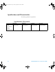
Technical data

N2780/81/82/83 User’s and Service Guide 17
This demagnetizes the core if it has been magnetized by
switching the power on and off, or by an excessive input.
Always carry out demagnetizing before measurement. The
demagnetizing process takes about one second. During
demagnetizing, a demagnetizing waveform is output.
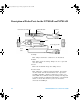
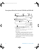
4 Zero adjustment dial (ZERO ADJ)
Use the zero adjustment dial to correct for the effect of a
voltage offset or temperature drift on the unit. The probe
should be always be zeroed after demagnetization.
5 Coarse adjustment trimmer
This adjustment should only be carried out if the probe
offset is outside the range of the zero adjustment dial.
6 BNC output connector
Connect to the BNC input connector of the oscilloscope.
7 Power plug
Connect this to the N2779A power supply receptacle to
supply power to the sensor terminator.
8 Barrier
This structure reduces the likelihood of touching the
conductor while testing, and indicates the limit of safe
physical contact. Avoid touching the clamp in front of the
barrier when clamping or measuring.
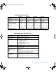
NOTE
The output of the current probe is terminated internally.
You must select the input impedance of the oscilloscope to
be 1 M in order to make accurate measurements. If the
oscilloscope you are using does not have a 1 M input
impedance setting you can purchase the Agilent E2697A
50 to 1 M adapter.
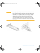
Turn the collar until it clicks, and check that it is locked
securely.
medium_standard.book Page 17 Friday, September 10, 2010 2:45 PM