
User guide

N4970A Operation Overview
16
PRBS Generator 10 Gb/s User Guide
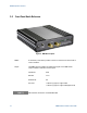
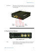
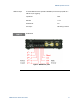
Rear connector: Eight sets of pins are provided to select the pattern length and mark density.
A separate pair of pins is provided to allow remote reset. Two jumpers are
used to select the desi
red pattern length and mark density. Install the jumpers
in the desired positions for stand-alone operation. Refer to Figure 5. A cable
can be connected to the pins for remote operation.
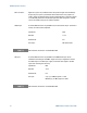
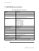
CKO output: A female SMA connector is pro
vided for the internal clock output. The clock is
factory-set and cannot be adjusted.
Impedance: 50 Ω
Max DC: ± 5 V
Nominal DC: 0 V
AC output: 600 mV nominal
ESD sensitive; terminate if unused. DC Blocked.
Clk input: A female SMA connector is provided for the PRBS clock input, which
establishes the timing of the PRBS. A rigid coax loop is supplied to connect
the CKO output to the CKI input; supply an external clock signal to the CKI
input after removing the coax loop.
Impedance: 50 Ω
Max DC: ± 5 V
Nominal DC: 0 V
AC input: 2 V p-p (+10 dBm) typical < 1 GHz
890 mV p-p (+3 dBm) typical ≥ 1 GHz
ESD sensitive; terminate if unused. DC Blocked.