
User guide

Operation
24
PRBS Generator 10 Gb/s User Guide
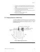
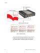
4.3 Resetting the N4970A
The reset pins on the back panel can be used to reset the N4970A without
using the front panel pushbutton switch. The design of the N4970A has the
pin below the "Reset" pin assigned to ground so tha
t an external reset switch
can be connected with a 2 pin connector. Refer to Figure 6.
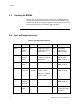
4.4 Input and Output Connectors
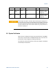
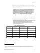
Table 3. Input and output connectors
Connector
Description
DC Level
DC Level
Z0
Notes
Data+ Data
positive
output
0 V >300 mV p-p typical
>750 mV p-p typical
(Option 010)
50 Ω DC blocked,
ESD sensitive,
SMA connector
Data– Data
negative
output
0 V > 300 mV p-p typical
> 750 mV p-p typical
(Option 010)
50 Ω DC blocked,
ESD sensitive,
SMA connector
CKO 10G clock
output
0 V >600 mV p-p nominal 50 Ω DC blocked,
SMA connector
CKI External
clock input
–5 V to
+5 V max
2 V p-p (+10 dBm)
typical < 1 GHz
890 mV p-p (+3 dBm)
typical ≥ 1 GHz
50 Ω DC blocked,
SMA connector
CKO/16 Clock
divided by
16 output
0 V >600 mV p-p nominal 50 Ω DC blocked,
SMA connector
P1 – P5 Pattern
select
N/A N/A N/A Selected by closure
to lower pin. Refer
to Figure 6